
Projection exposure apparatus, cleaning and maintenance methods of a projection exposure apparatus, and device manufacturing method

a technology of exposure apparatus and cleaning and maintenance methods, which is applied in the direction of printing, cleaning using liquids, instruments, etc., can solve the problems of deterioration of performance of liquid immersion exposure apparatus, insufficient margin during exposure operation, and too narrow depth of focus, etc., and achieve excellent device and good yield

Active Publication Date: 2006-10-19
NIKON CORP
View PDF17 Cites 93 Cited by
  • Summary
  • Abstract
  • Description
  • Claims
  • Application Information

AI Technical Summary

Benefits of technology

[0014] The purpose of the present invention is to prevent performance deterioration of the projection exposure apparatus that has applied the liquid immersion method.

Problems solved by technology

In addition, in order to handle further high integration of semiconductor integrated circuits, even shorter exposure wavelengths are being researched, and with the current situation there is concern that the depth of focus will become too narrow, and the margin during the exposure operation will be insufficient.
In liquid immersion type projection exposure apparatuses, there is a possibility that impurities dissolved in the liquid will precipitate and accumulate in the piping and / or at the front end portion of the projection optical system, which comes into contact with the liquid, leading to deterioration of performance as a liquid immersion type exposure apparatus.
Particularly, the fluorite (CaF2) and barium fluoride (BaF2), for example, that can be used as the lens material at ultraviolet wavelengths may be eroded, if purified water or an aqueous solution is used as the liquid due to the solubility thereof, and the concentration of calcium ions and barium ions, known as the scale component, in the liquid increases, and, as a result, due to precipitation and accumulation of the scale, there is a possibility that deterioration of performance as a liquid immersion type exposure apparatus would accelerate.

Method used


Image

  • Projection exposure apparatus, cleaning and maintenance methods of a projection exposure apparatus, and device manufacturing method
  • Projection exposure apparatus, cleaning and maintenance methods of a projection exposure apparatus, and device manufacturing method
  • Projection exposure apparatus, cleaning and maintenance methods of a projection exposure apparatus, and device manufacturing method

Examples


first embodiment

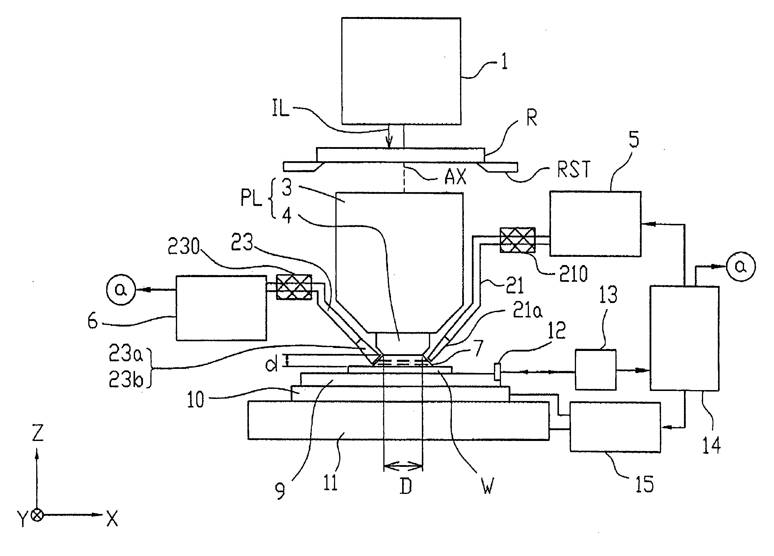
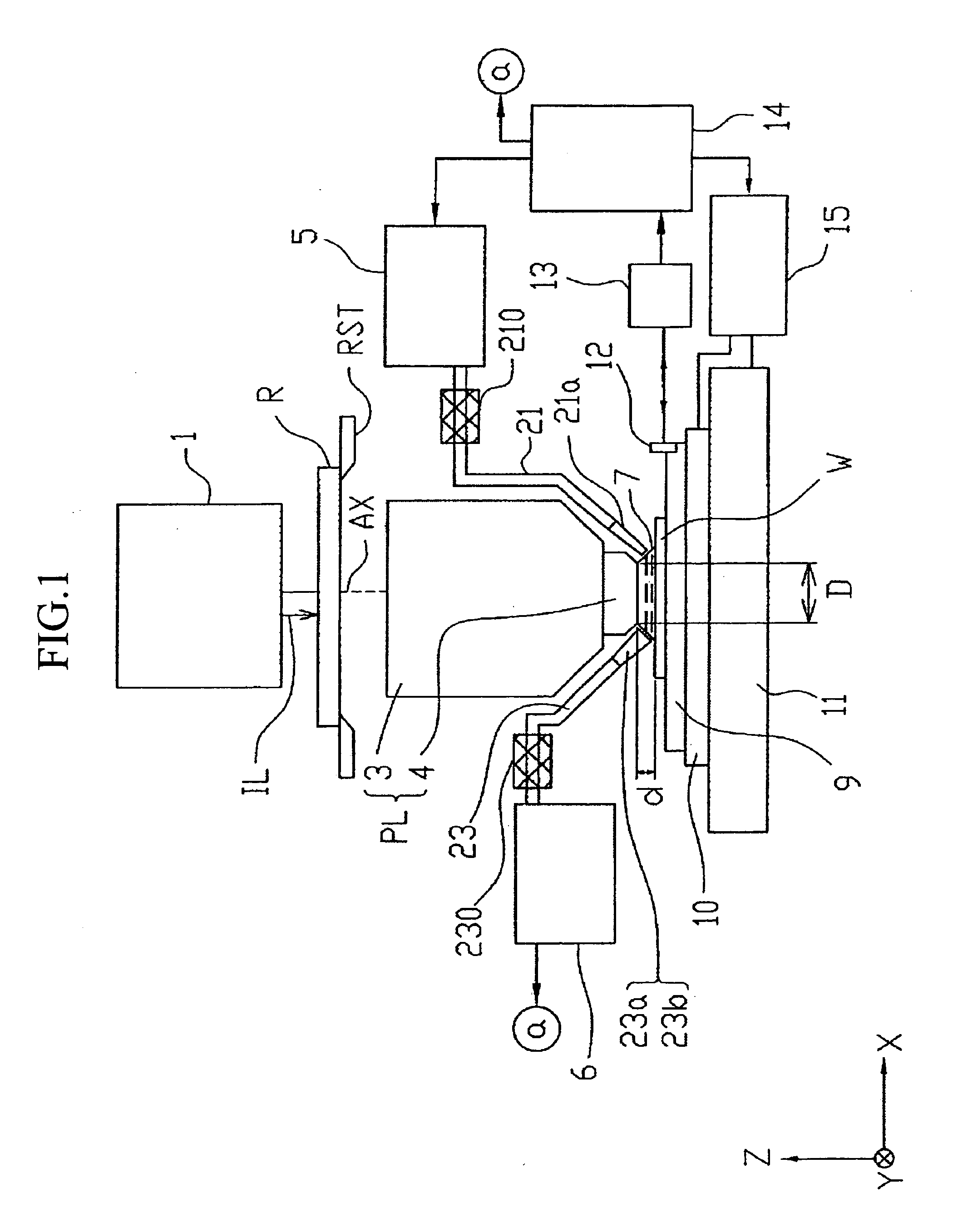
[0076] According to the projection exposure apparatus relating to the first embodiment, because the scale adhesion prevention mechanisms of the supply tube that supplies the liquid are provided respectively, the scale component dissolved in the liquid is neutrally or negatively charged when the liquid flows through the supply tube, and it is possible to prevent scale from adhering to the inner walls of the supply tube or the nozzle, etc. Therefore, it is possible to prevent the flow of liquid from worsening due to the adherence of scale to the inner walls of the supply tube and the recovery tube and to prevent nozzles that supply or discharge liquid from clogging due to scale. Furthermore, it is also possible to prevent optical characteristics from deteriorating due to scale adhering to the front end portion of the projection optical system, so it is possible to stably maintain the performance of the projection exposure apparatus.

[0077] In addition, because the scale adhesion preven...

second embodiment

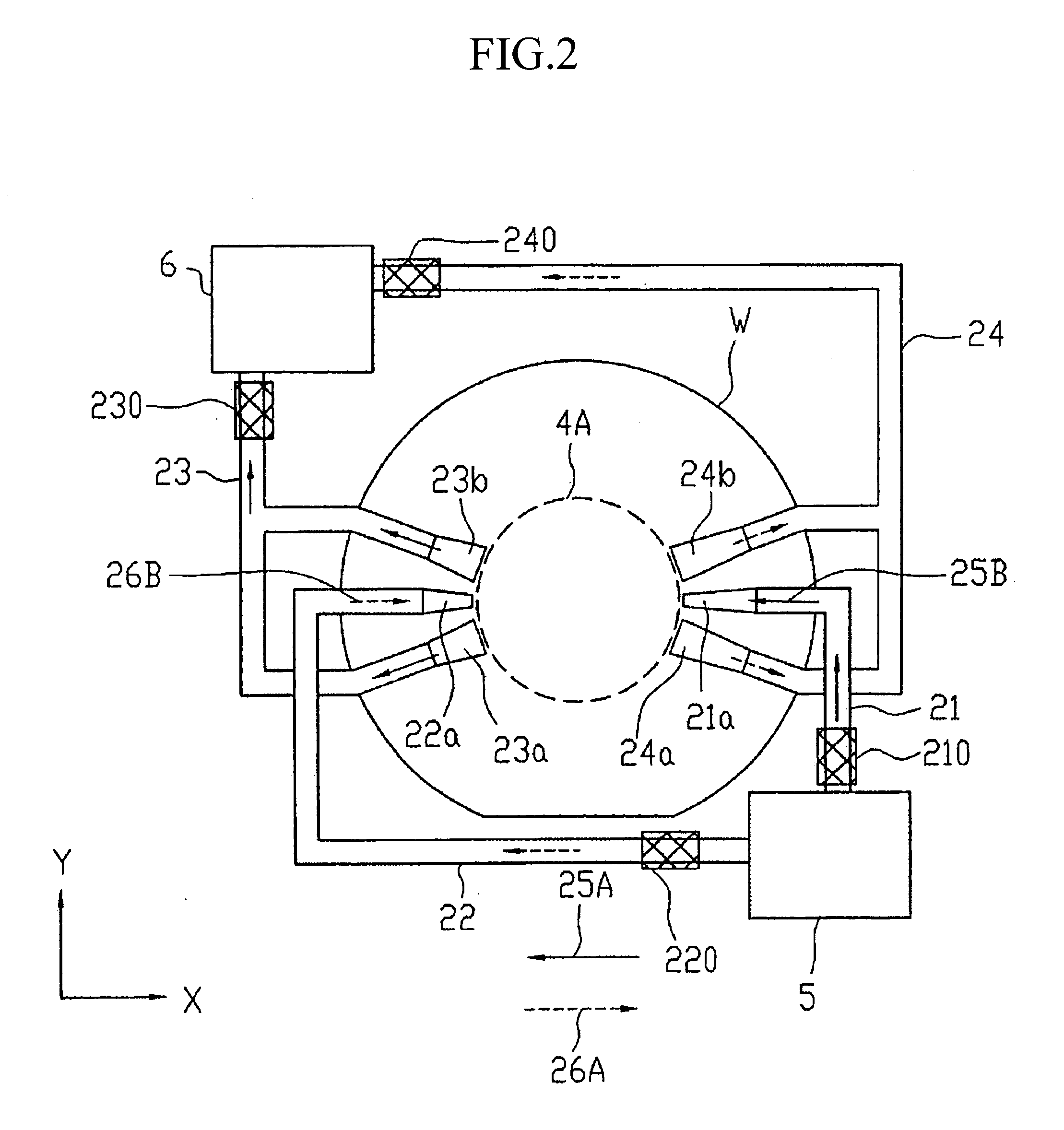
[0096] According to the scanning type projection exposure apparatus relating to the second embodiment, in the scale adhesion prevention mechanisms respectively provided on the supply tube and the recovery tube, the scale component dissolved in the liquid is neutrally or negatively charged, so it is possible to prevent the adhesion of scale to the inner walls of the supply tube and the recovery tube and / or to the nozzles that supply and discharge the liquid. Therefore, the flow of liquid within the supply tube or the recovery tube is always fixedly maintained, so it is possible to continue to stably fill the space between the optical element and the wafer with the liquid.

[0097] In addition, the index of refraction n of purified water with respect to exposure light whose wavelength is approximately 200 nm is approximately 1.44, and ArF excimer laser light, which has a 193 nm wavelength, is shortened to 1 / n, that is, approximately 134 nm, on the wafer W, so it is possible to obtain hig...

third embodiment

[0120] Next, cleaning of the liquid flow path will be explained. Cleaning of the liquid flow path in the third embodiment is implemented by causing the liquid supply flow volume to fluctuate over time. By performing this type of cleaning, substances that become causes of solid matter such as salts dissolved in the liquid are removed, and adherence of the solid matter to the walls in the flow path is prevented.

[0121] Basic operations of the flow volume fluctuation control unit 122 at the time of an increase in the liquid supply flow volume will be explained. The flow volume fluctuation control unit 122 manages the pressurization value and timing for changing the liquid supply flow volume. That is, the flow volume fluctuation control unit 122 sends pressurization signals corresponding to the liquid supply flow volume one would like to increase to the liquid supply mechanism 111 at a prescribed time. The liquid supply mechanism 111 that has received the pressurization signals from the ...


PUM


Abstract

A projection exposure apparatus that exposes a substrate with a liquid interposed between a surface of the substrate and an optical element on the substrate side of a projection optical system; includes liquid supply and discharge mechanisms, which supply the liquid via a liquid supply tube as they recover the liquid via a liquid recovery tube, and an adhesion preventing mechanism that prevents an adhesion of impurities on member forming a flow path for the liquid.

Description

CROSS-REFERENCE TO RELATED APPLICATION [0001] This is a Continuation Application of International Application No. PCT / JP2004 / 013906, filed Sep. 24, 2004, which claims priority to Japanese Patent Application Nos. 2003-335691 (filed Sep. 26, 2003) and 2003-339625 (filed Sep. 30, 2003). The contents of the aforementioned application are incorporated herein by reference.BACKGROUND OF THE INVENTION [0002] 1. Field of the Invention [0003] The present invention relates to a projection exposure apparatus used to transfer a mask pattern onto a photosensitive substrate by a lithography process for manufacturing devices such as semiconductor elements, image pickup elements (such as CCDs), liquid crystal display elements or thin film magnetic heads, a cleaning method and a maintenance method for a liquid immersion type projection exposure apparatus, and a device manufacturing method. [0004] 2. Description of Related Art [0005] A projection exposure apparatus is used that, when a semiconductor e...

Claims


Application Information

Patent Timeline
IPC IPC(8): G03B27/42G03F7/20H01L21/027
CPCG03F7/2041G03F7/70341G03F7/70975G03F7/70925G03F7/70916B08B3/10H01L21/0274
Inventor TANI, YASUHISASHIOZAWA, MASAKI
Owner NIKON CORP
Learn More