
Optical film, method for producing the same, and image display device using the same

Inactive Publication Date: 2006-08-17
NITTO DENKO CORP
View PDF11 Cites 39 Cited by
  • Summary
  • Abstract
  • Description
  • Claims
  • Application Information

AI Technical Summary

Benefits of technology

[0005] Therefore, with the foregoing in mind, it is an object of the present invention to provide an optical film being excellent in adhesiveness between its base and its birefringent layer.
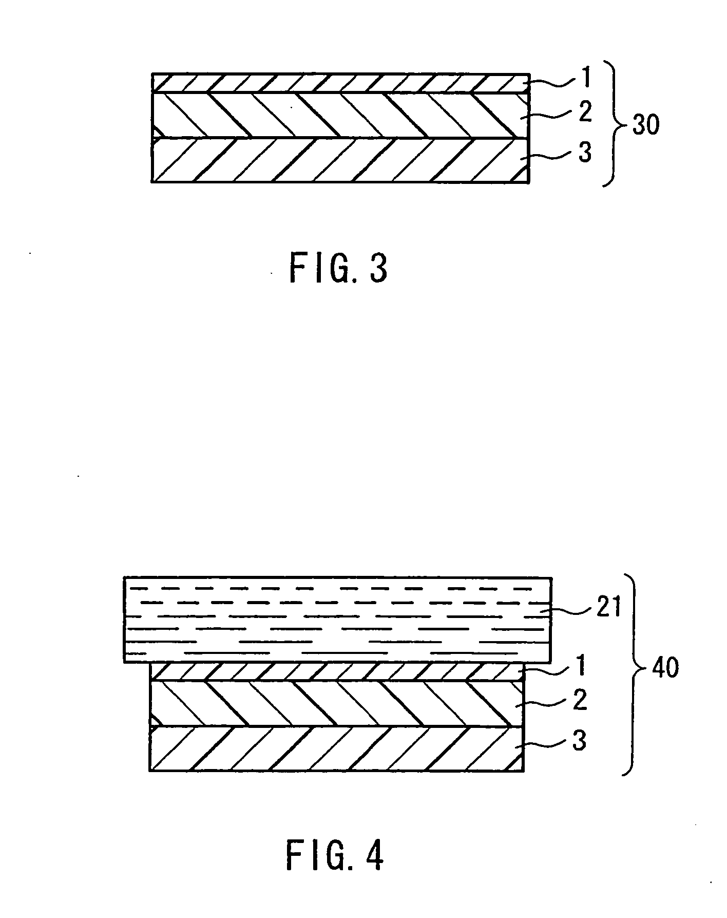
[0007] In this manner, a coating solution for forming the birefringent layer is prepared by using a solvent exhibiting solubility with respect to the base, and the thus prepared solution is coated on the base so that the solvent in the solution is infiltrated through the surface of the base. As a result of the infiltration of the solvent into a part of the base, adhesiveness between the base and the birefringent layer formed on the base will be improved. The inventors of the present invention were the first to find that the adhesiveness can be improved in this manner. It is considered that the adhesiveness between the base and the birefringent layer can be improved by this method as a result of the infiltration of the solvent due to the following reasons. That is, 1) the surface of the base is dissolved partially by the solvent and roughened, and thus an area contacted with the birefringent layer is increased to improve adhesiveness; 2) molecular disposition of the base changes due to the dissolution of the base, and thus the adhesiveness with the birefringent layer is improved; or 3) the base surface is melted by the solvent so as to form a compatible layer (a layer where base ingredients, the solvent and the material of the birefringent layer are mixed) between the base and the birefringent layer so as to improve the adhesiveness. Due to the excellent adhesiveness between the base and the birefringent layer, when an optical film produced according to the present invention is used for an image display device such as a liquid crystal display or the like, it can provide some effects that cannot be obtained in conventional techniques, that is, optical distortion is prevented and a preferable visibility is provided.

Problems solved by technology

However, such a lamination type retardation film has some problems as described below.
For example, though such a lamination retardation film includes a birefringent layer formed on a base, adhesiveness between the base and the birefringent layer is insufficient in many cases, and thus the birefringent layer may be peeled off under a heating condition, a humidifying condition, a cooling condition or the like.
As a result, in a case of assembling the lamination retardation film in an image display device such as a liquid crystal display, the above-mentioned peeling can cause optical distortion and degrade the display quality.

Method used


Image

  • Optical film, method for producing the same, and image display device using the same
  • Optical film, method for producing the same, and image display device using the same
  • Optical film, method for producing the same, and image display device using the same

Examples


example 1

[0166] Polyimide having molecular weight (Mw) of 110,000, which is represented by the below-mentioned formula, was synthesized from 2,2-bis(3,4-dicarboxyphenyl)hexafluoropropane dianhydride and 2,2′-bis(trifluoromethyl)-4,4′-diaminobiphenyl, and dissolved in ethyl acetate so as to prepare a 20 wt % polyimide solution. Regarding the preparation of polyimide or the like, description of “Polymer” 40 (1999) 4571-4583, F. Li et al. was referenced to. A triacetylcellulose (TAC) film with a thickness of 80 μm was stretched 1.3 times its original length in the transverse direction by fixed-end transverse stretching at 175° C., thereby a stretched TAC film with a thickness of 78 μm was obtained. The thus stretched TAC film was coated with the polyimide solution, and heat-treated for 10 minutes at 150° C. so as to obtain an optical film. The optical film includes a completely transparent and flat stretched TAC film (a base (b)) with a thickness of 78 μm and Δn(b) of approximately 0.0006, and ...

example 2

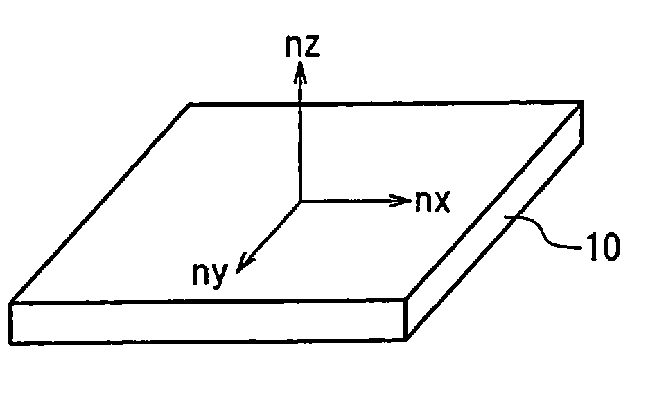
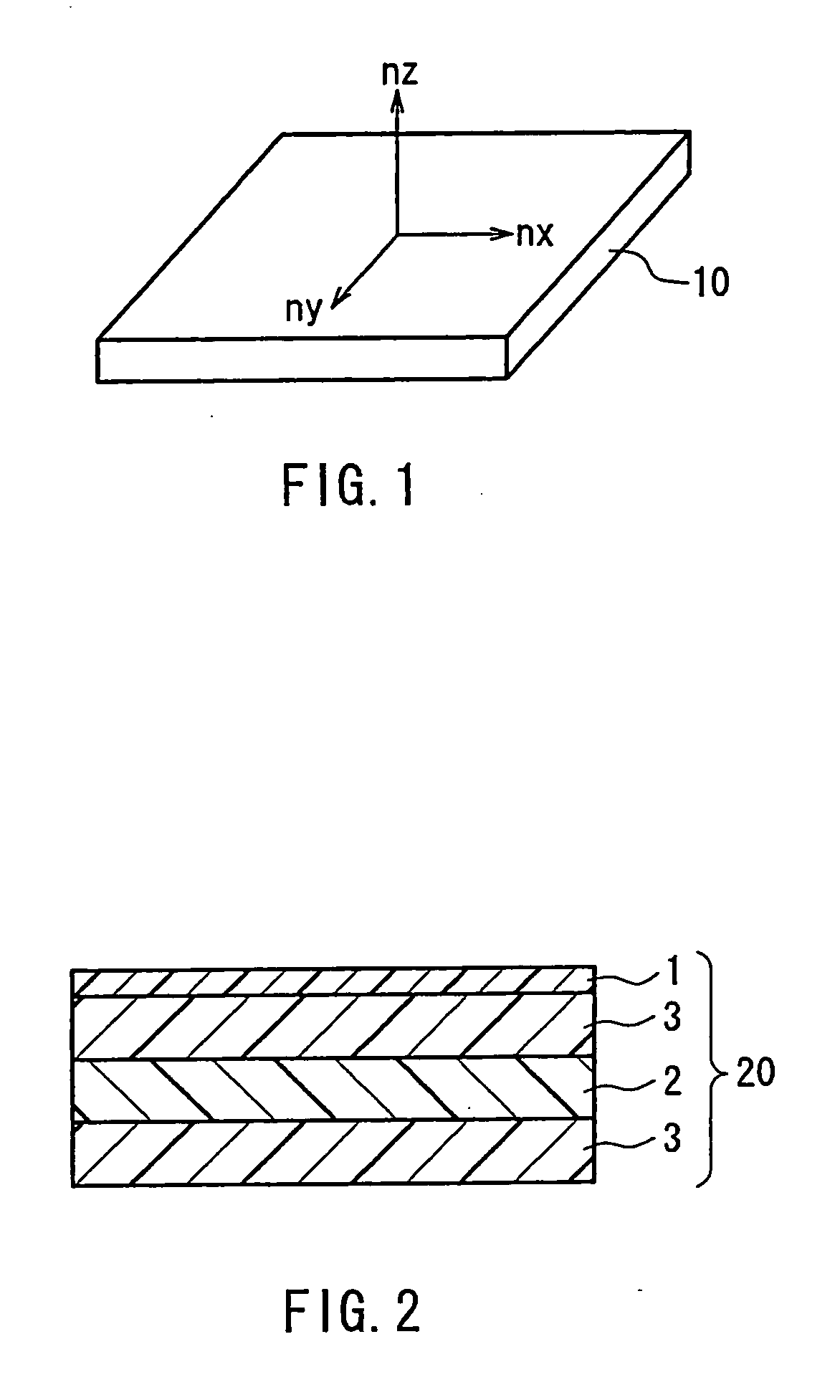
[0167] Polyetherketone (trade name: Polyetherketone A manufactured by Nippon Shokubai Co., Ltd.) having molecular weight (Mw) of 110,000 represented by the below-mentioned figure (18) was dissolved in methyl isobutyl ketone so as to prepare a 20 wt % varnish. This varnish was coated on a stretched TAC film as in Example 1, and dried for 20 minutes at 150° C. so as to obtain an optical film. The optical film included a completely transparent and flat stretched TAC film (a transparent film (b)) with a thickness of 78 μm and a Δn(b) of approximately 0.0006, and a polyether ketone film (a birefringent layer (a)) with a thickness of 4 μm and a Δn(a) of approximately 0.038, laminated on the transparent film (b). This optical film included a birefringent layer having an optical property of nx>ny>nz.

example 3

[0168] Polyimide (Mw=30,000) was synthesized from 4,4′-bis(3,4-dicarboxyphenyl)-2,2-diphenylpropane dianhydride and 2,2′-dichrolo-4,4′-diaminobiphenyl, and dissolved in cyclopentanone so as to prepare a 20 wt % polyimide solution. This solution was coated on an unstretched TAC film with a thickness of 80 μm, dried for 5 minutes at 130° C., and stretched 1.1 times its original length by longitudinal uniaxial stretching at 150° C. so as to obtain an optical film. The optical film included a completely transparent and flat TAC film (a transparent film (b)) with a thickness of 78 μm and a Δn(b) of approximately 0.0006, and a polyimide film (a birefringent layer (a)) with a thickness of 5 μm and a Δn(a) of approximately 0.025, being laminated on the transparent film (b). This optical film included a birefringent layer having an optical property of nx>ny>nz.


PUM

PropertyMeasurementUnit
Thicknessaaaaaaaaaa
Solubility (mass)aaaaaaaaaa
Adhesivityaaaaaaaaaa

Abstract

An optical film, which includes a laminate of a base and a birefringent layer, and which is excellent in adhesiveness between the base and the birefringent layer, is provided. The birefringent layer is formed on the base by: coating a material of the birefringent layer on the base so as to form a coating film; stretching / shrinking the base so as to stretch / shrink the coating film; and solidifying the material of the coating film. The material is dispersed or dissolved previously in a solvent and coated in a form of solution, where the solvent used exhibits solubility with respect to the base, and in the coating step, the solvent is infiltrated into a part of the interior of the base, thereby obtaining an optical film with excellent adhesiveness between the base and the birefringent layer.

Description

TECHNICAL FIELD [0001] The present invention relates to an optical film, a method for producing the same, and various image display devices using the same. BACKGROUND ART [0002] Conventionally, various retardation plates have been used for optical compensation in various liquid crystal displays. An example of the retardation plates is an optically-biaxial retardation plate, and it can be produced in general by any of various polymer-film stretching methods (see JP3(1991)-33719 A, for example) like roller tensile stretching, roller press stretching, and tenter transverse uniaxial stretching, or a method of providing anisotropy through biaxial stretching (see JP3(1991)-24502 A, for example). Additional examples include a retardation plate in which a uniaxially stretched polymer film having a positive optical anisotropy and a biaxially stretched polymer film having a negative optical anisotropy and whose in-plane retardation is small are used in combination (see JP4(1992)-194820 A, for...

Claims


Application Information

Patent Timeline
IPC IPC(8): C09K19/00B29C55/02B32B7/02C08J7/04G02B5/30G02F1/13363H01L51/50H05B33/02
CPCB29C55/026B29K2995/0032Y10T428/10G02F1/13363Y10T428/1036G02B5/3083C09K2323/00C09K2323/03B32B2307/42G02B5/3041
Inventor MURAKAMI, NAONISHIKOUJI, YUUICHIYOSHIMI, HIROYUKI
Owner NITTO DENKO CORP
Learn More