Eureka AIR delivers breakthrough ideas for toughest innovation challenges, trusted by R&D personnel around the world.

Electrochemical oxygen generator module assembly

a technology of electrochemical oxygen generator and module, which is applied in the direction of electrochemical machining apparatus, specific gas purification/separation, inorganic chemistry, etc., can solve the problems of high leakage risk of joints, general inability of current oxygen generating systems to deliver high-pressure oxygen above 1800 psi, etc., and achieve the effect of increasing oxygen-generating capacity

Active Publication Date: 2006-08-10
COBHAM MISSION SYST DAVENPORT LSS INC
View PDF6 Cites 59 Cited by
  • Summary
  • Abstract
  • Description
  • Claims
  • Application Information

AI Technical Summary

Benefits of technology

[0009] A ceramic element is provided which can be injection molded from an electrolyte and a binder. The ceramic element includes a tube support portion and a plurality of tubes extending from the tube support portion. The plurality of tubes is arranged in rows and columns. A plurality of vias extends from one surface of the tube support portion to and opposite surface of the tube support portion. The ceramic element is coated with an electrically conductive coating and a current collector coating. The vias are coated with the electrically conductive coating and plugged. After the coatings are removed in selected areas of the ceramic element, the tubes of the ceramic element form a series-parallel array because tubes in the same column are connected in parallel electrically and tubes in adjacent rows are connected in series electrically. Two ceramic elements are sealed together to form an Integrated Manifold and Tube (IMAT) that creates a separate modular electrochemical device. The electrochemical device can be either an oxygen generator or a fuel cell. Manifolding together two or more modular oxygen generators can increase oxygen-generating capacity.

Problems solved by technology

However, current oxygen generating systems are generally unable to deliver high-pressure oxygen above 1800 psi.
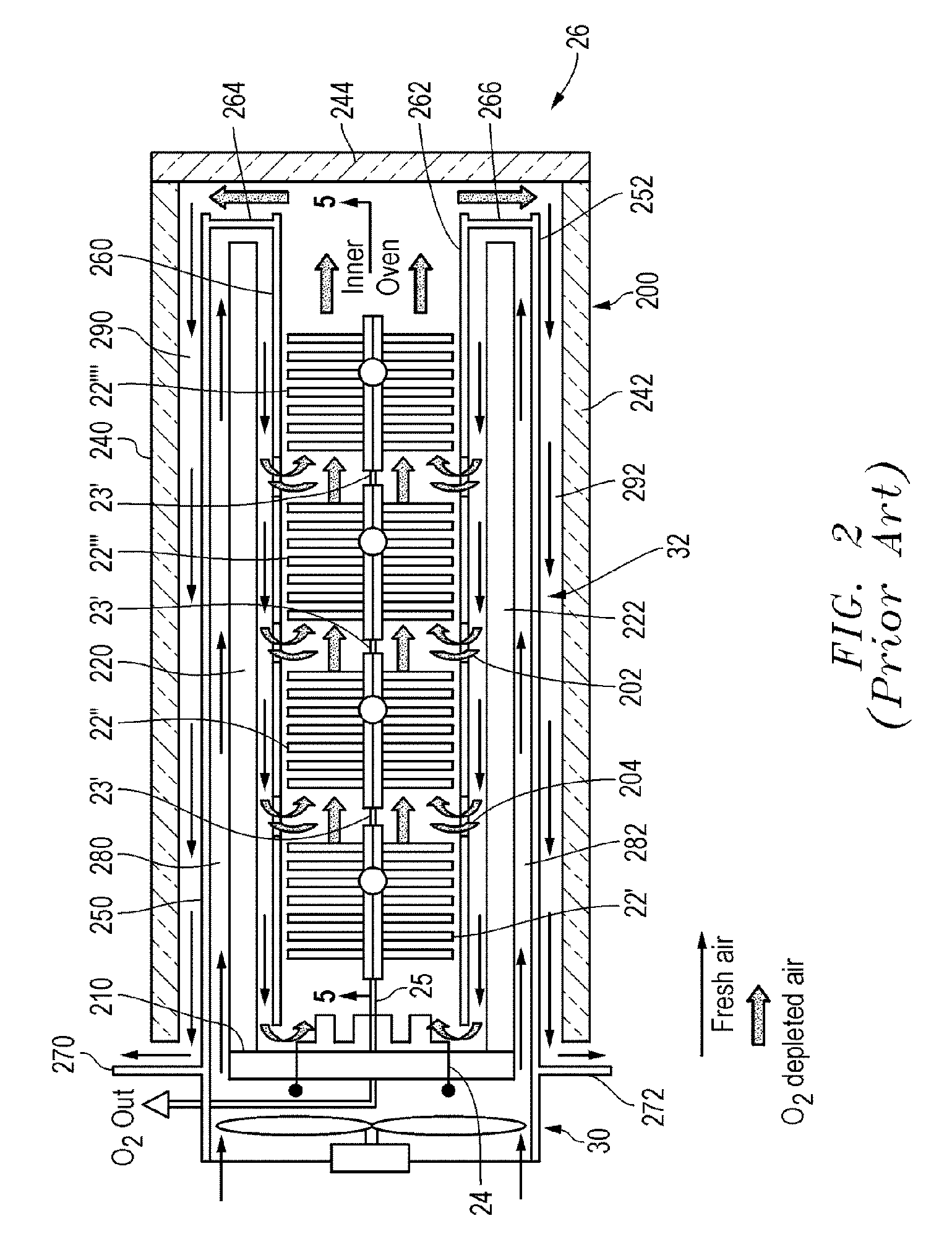
However, such prior IMAT designs and mounting methods required a spherical joint between one IMAT unit and a metal tube extending out of the oven.
Such joints are all highly susceptible to leakage, and are very expensive.

Method used


Image

  • Electrochemical oxygen generator module assembly
  • Electrochemical oxygen generator module assembly
  • Electrochemical oxygen generator module assembly

Examples


Embodiment Construction

[0027] So that the manner in which the above recited features, advantages, and objects of the present invention are attained can be understood in detail, more particular description of the invention, briefly summarized above, may be had by reference to the embodiment thereof that is illustrated in the appended drawings. In all the drawings, identical numbers represent the same elements.

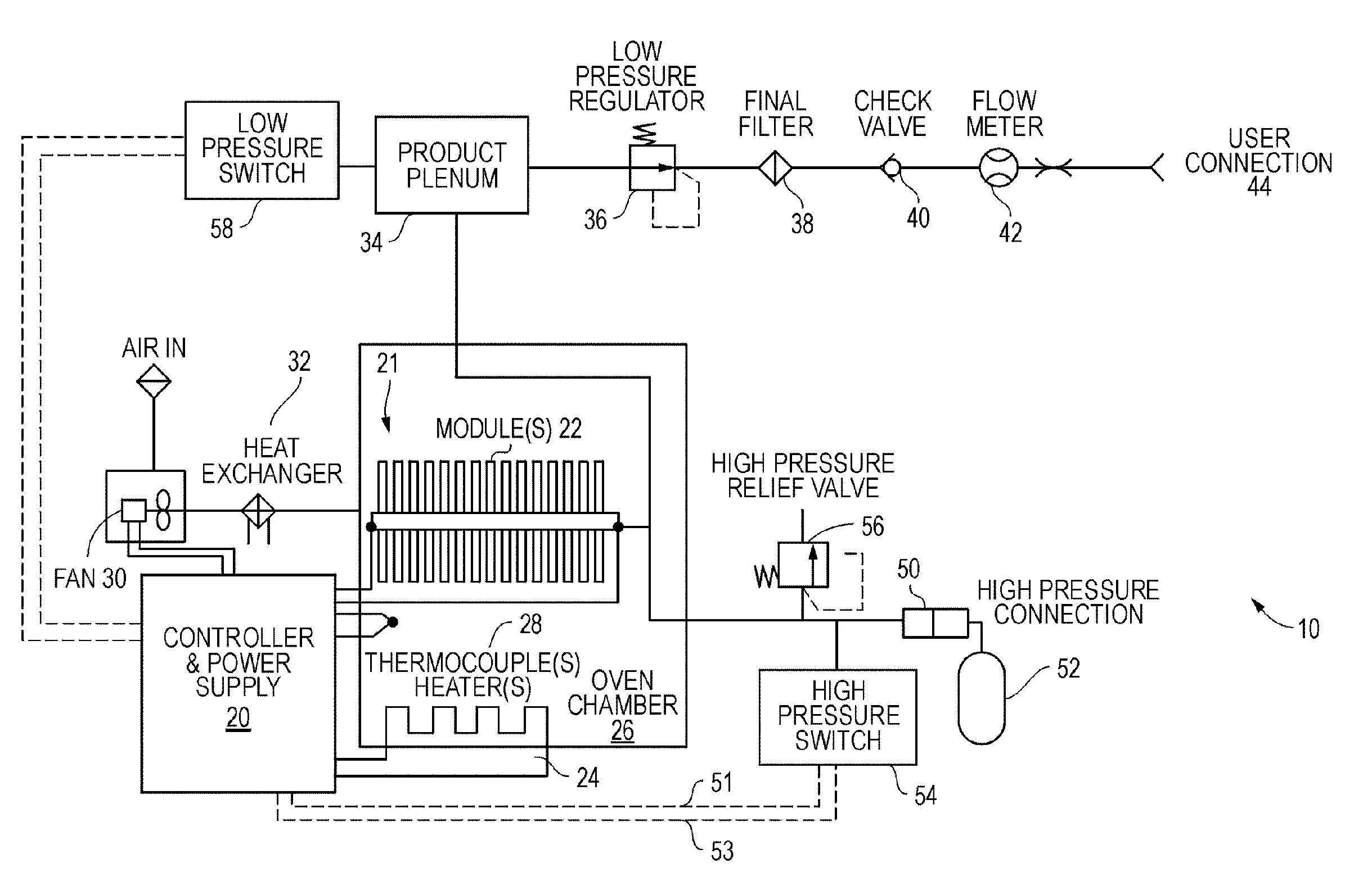
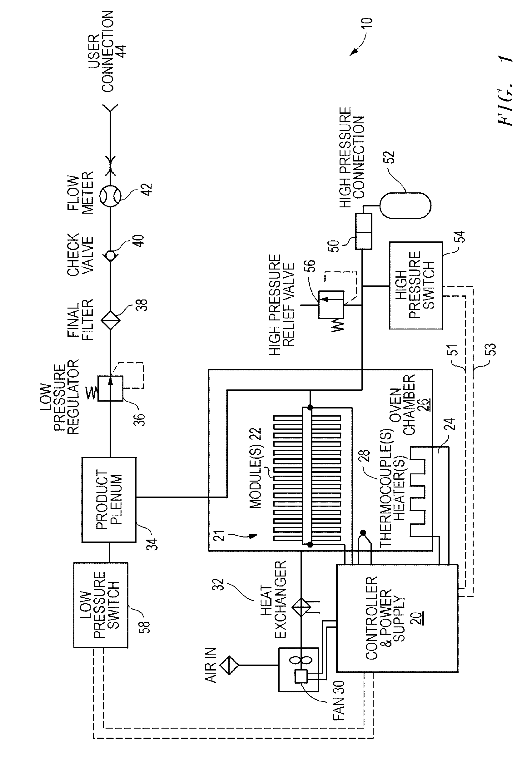
[0028]FIG. 1 illustrates a known schematic of a complete oxygen generating system 10 utilizing an electrochemical oxygen generator in the form of a modular ceramic oxygen generator. This schematic depicts a power supply and controller 20 that supplies electrical power to an oven heater 24 to raise the temperature within the operating range of an oxygen generating module assembly 22. The oxygen generating IMAT module 22 assembly can include one or more oxygen generating modules such as those disclosed in U.S. Pat. Nos. 5,871,624 and 5,985,113 and as will be describe below.

[0029] The temperature range...


PUM

PropertyMeasurementUnit
Electrical conductoraaaaaaaaaa

Abstract

An ionically conductive ceramic element includes a central unit (703). The central unit (703) is composed of a plurality of integrated manifold and tube modules (IMAT) (22) joined end to end along a central axis (A). Each IMAT module (22) has a tube support portion (804) and a plurality of tubes (802) extending from the first surface (803). The tubes (802) each have a closed end (805) and an open end. The second surface (807) is at least partially open to the atmosphere. The open ends of the tubes (802) are open to the atmosphere through the second surface (807). An interior space (830) is formed in the interior of the IMAT (22) for collecting a desired product gas. A collection tube (710) is operable joined with a first end (714) of the central unit (703) for transporting the desired product gas collected in the interior space (730) of the connected IMAT modules (22).

Description

CROSS REFERENCE TO RELATED APPLICATIONS [0001] This application claims the benefit of U.S. Provisional Application Ser. No. 60 / 593,713, filed Feb. 8, 2005, entitled ELECTROCHEMICAL OXYGEN GENERATOR MODULE ASSEMBLY.BACKGROUND OF THE INVENTION [0002] 1. Technical Field [0003] The invention relates to the field of devices for separating oxygen from a more complex gas containing oxygen to deliver separated oxygen for use. More particularly, the invention relates to solid state electrochemical devices for separating oxygen from a more complex gas. [0004] 2. Background Art [0005] It is well known, and has been demonstrated, that oxygen can be removed from more complex gasses, such as air, by an electrochemical process of ionizing the oxygen molecules, transporting the oxygen ions through a solid electrolyte and reforming the oxygen molecules on an opposite electrolyte surface. An electrical potential is applied to a suitable catalyzing electrode coating applied to the surface of the elect...

Claims


Application Information

Patent Timeline
IPC IPC(8): C25B1/02
CPCB01D53/22B01D63/00B01D2257/104B01D2313/18B01D2313/38C01B13/0251C01B2210/0046B01D2313/221C25B1/02
Inventor BAGBY, BRAD M.HARVEY, SCOTT H.
Owner COBHAM MISSION SYST DAVENPORT LSS INC
Why Eureka
Eureka Blog
Learn More