
Mixer blade attachment with flexible fins

Active Publication Date: 2006-08-03
FRUT
View PDF28 Cites 59 Cited by
  • Summary
  • Abstract
  • Description
  • Claims
  • Application Information

AI Technical Summary

Benefits of technology

[0007] As a result, a need exists to provide an improved mixer blade that overcomes the above mentioned problems. A need exists for mixing ingredients in a consistent and uniform way while not damaging the container that contains the ingredients.
[0008] In accordance with one preferred embodiment of the present invention, an attachment for wiping a mixture from the sides of a container may be easily applied to a pre-existing mixer blade.
[0010] The attachment may contain angular flexible fins for pushing the mixture to the center of the container. The fins may be used for lifting the mixture located in the center of the container. The fins may be made of a flexible material for providing smooth contact between the fins and the container.
[0011] The mixer blade attachment with flexible fins may provide a uniform and consistent mixture. The mixer blade attachment with the flexible fins is easy to clean.
[0012] In accordance with one embodiment of the present invention, an attachment for a mixer blade is described. The attachment allows for the smooth contact between the mixer blade and the container without damaging the container. The angular direction of the fins directs materials in the container downward. By directing material downward, the attachment gives the mixture uniformity and consistency.

Problems solved by technology

In any of the previous described mixers, when mixing some of the ingredients may cling to the inside wall of the container so that the final product is improperly mixed or does not have the correct ratio of ingredients mixed uniformly and consistently throughout the product.
This poses a problem because users may have to consistently scrape the sides of the container.
Users expose themselves to danger when the spoon or the like may catch in the mixer blade.
This results in delay and inconvenience.
Additionally, when users attempt to mix ingredients by repositioning the mixer blade, damage may occur when the mixer blade touches the side of the container.
However, these inventions do not direct the flow of the mixture.
Thus, the mixture is not uniform or consistent.

Method used


Image

  • Mixer blade attachment with flexible fins
  • Mixer blade attachment with flexible fins
  • Mixer blade attachment with flexible fins

Examples


Embodiment Construction

)

[0025] Referring to the Figures, an attachment to a mixer blade will be described. Like numbers are used to identify like parts.

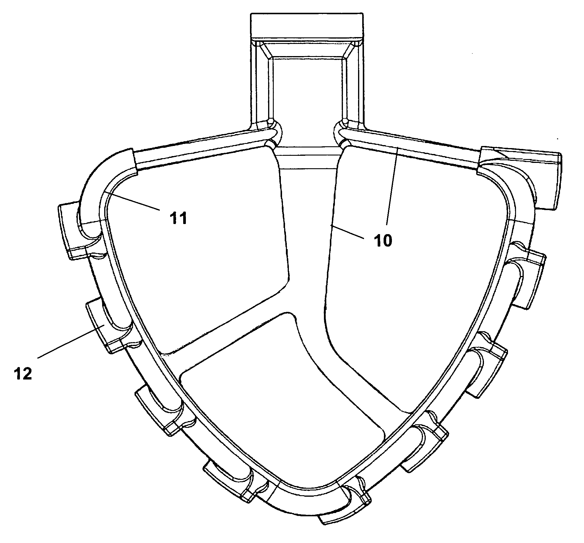
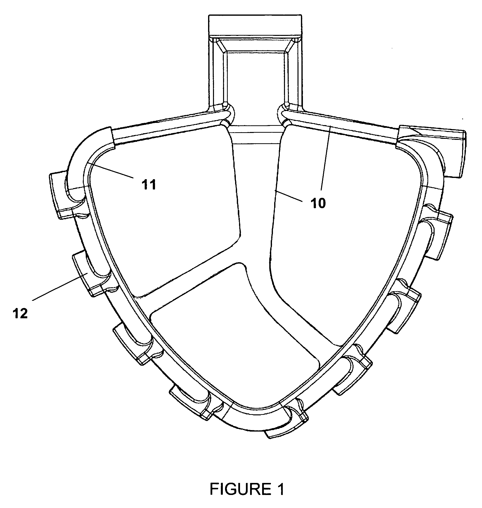
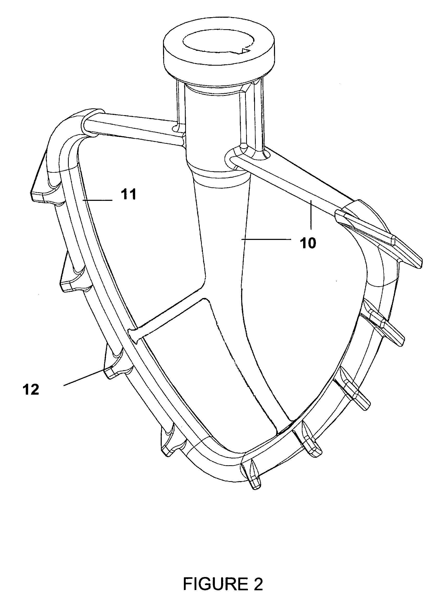
[0026]FIGS. 1-7 show an embodiment of a mixer blade with an attachment that may comprise a rigid mixing blade structure 10. Encasing the mixing blade 10 is an over molded elastomeric sheath 11. Integral to the sheath 11 are a plurality of elastomeric fins 12. The fins 12 may be spaced along the sheath 11. The fins may be placed at an angle. It is envisioned that one may attach the fins directly to the mixer blade without the use of an elastomeric sheath.

[0027] Once the sheath 11 is placed on the mixer blade 10 either permanently or temporarily, the mixer blade 10 may use the flexible fins 12 to push the mixture downward. The flexible fins 12 may be positioned at an angle and may be spaced completely around the elastomeric sheath 11.

[0028] As is shown in FIGS. 4 and 5, showing the left and right side view of the mixer blade with attachment, the fins 12 a...


PUM


Abstract

The present invention is an attachment to a mixer blade for wiping the sides of a container and producing a mixture that is uniform and consistent. The attachment is placed onto the mixer blade either temporarily or permanently. After the attachment is on the mixer blade, the rotating spin of the mixer blade and the angular positioning of the flexible fins wipe the mixture on the sides of the container to the center of the container. By using a flexible material for the fins, the fins come into direct contact with the container while not damaging the container. The direct contact allows for the complete wiping of each side of the container. The attachment is easily cleaned.

Description

[0001] This application claims the benefit of U.S. Provisional Application Ser. No. 60 / 648,614, filed on Jan. 31, 2005, which is incorporated herein by reference.FIELD OF THE INVENTION [0002] This invention relates generally to mixer blades and more specifically, to mixer blades with an attachment with flexible fins for wiping the sides of a container. BACKGROUND AND SUMMARY OF THE INVENTION [0003] Mixers come in a variety of styles. There are many types of mixers ranging from hand held appliances to large mixers for commercial use. In some applications of mixers, a single blade is used for mixing material in a container. The mixer blade rotates and hovers in a position right above the container to mix the material. In other applications, the mixer has two beaters. [0004] Preferably, the mixer blade is composed of plastic or metal or other rigid material. The rigid material provides for sturdy attachment to the mixer. The attachable / detachable mixer blades may be removed from the mi...

Claims


Application Information

Patent Timeline
IPC IPC(8): B01F7/18B01F15/00
CPCA47J43/0711B01F7/00208B01F7/00316B01F7/00583B01F7/16B08B9/0808B01F27/091B01F27/11253B01F27/13B01F27/80
Inventor BUSICK, LOUIS M.
Owner FRUT
Learn More