Printer device and control method thereof

Active Publication Date: 2006-07-06
OCE TECH
View PDF2 Cites 5 Cited by
  • Summary
  • Abstract
  • Description
  • Claims
  • Application Information

AI Technical Summary

Benefits of technology

[0011] Thus, it is an object of an embodiment of the invention to control a scanning type bi-directional printing system when operating in a multiple printing stage mode such as to overcome or at least reduce gloss variations in a printed image while limiting the influence on productivity.
[0017] In an embodiment of the invention, the selected active portion for a forward traverse is different from the selected active portion for a backward traverse. Preferably a same active portion is selected for each forward traverse, while also a same active portion is selected for a backward traverse. This is believed to reduce print strategy complexity and to be less prone to errors. For instance, the active portion in a forward traverse may be either the upper part or the lower part of the print head while the active portion in a backward traverse is the other one of said upper part or said lower part of the print head.
[0019] In another embodiment of the invention, a print mask is employed defining an even number of printing stages. In that case each active portion may be selected such that the swath width of each printed portion of an image is equal. An advantage hereof is that such print strategy in most cases achieves a higher print productivity, since a higher number of nozzles can be image-wise activated.

Problems solved by technology

Both “interlace systems” and “multi-pass systems” as well as combinations thereof share the advantage of an improved image quality but also the inherent disadvantage of a lower productivity because multiple printing stages are required to render an image part.
Such systems are known to be sensitive to gloss variations.
This is believed to cause significant gloss variations in the printed images.

Method used


Image

  • Printer device and control method thereof
  • Printer device and control method thereof
  • Printer device and control method thereof

Examples


example 1

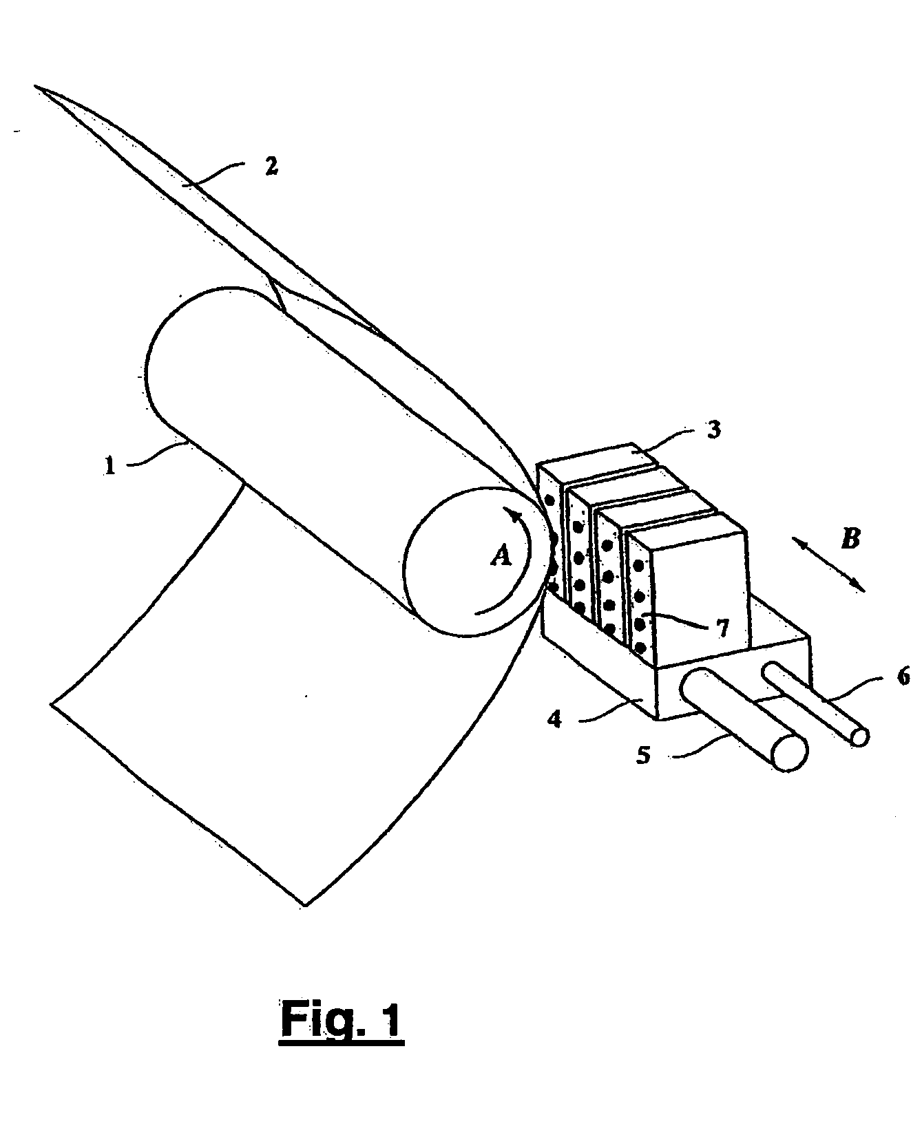
[0034] A printing device as depicted in FIG. 1 is used to reproduce a digital image. Each print head is provided with 24 discharging elements, i.e. nozzles, arranged in a single linear array, instead of using the print heads 3 provided with four discharging elements as in FIG. 1. The nozzles are positioned equidistant at a resolution of 300 npi (nozzles per inch). This means that the nozzle pitch or element pitch, being the distance between the centers of two adjacent nozzles is about 85 μm.

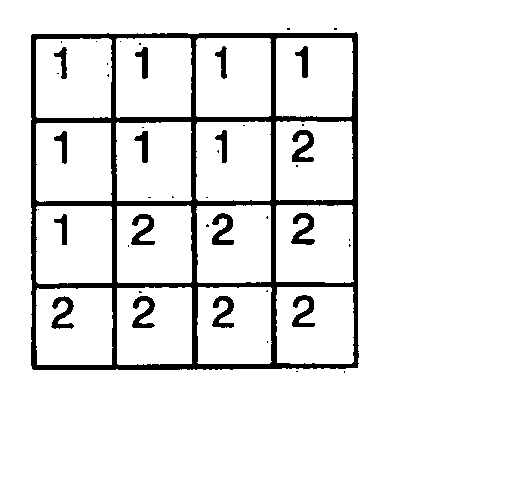
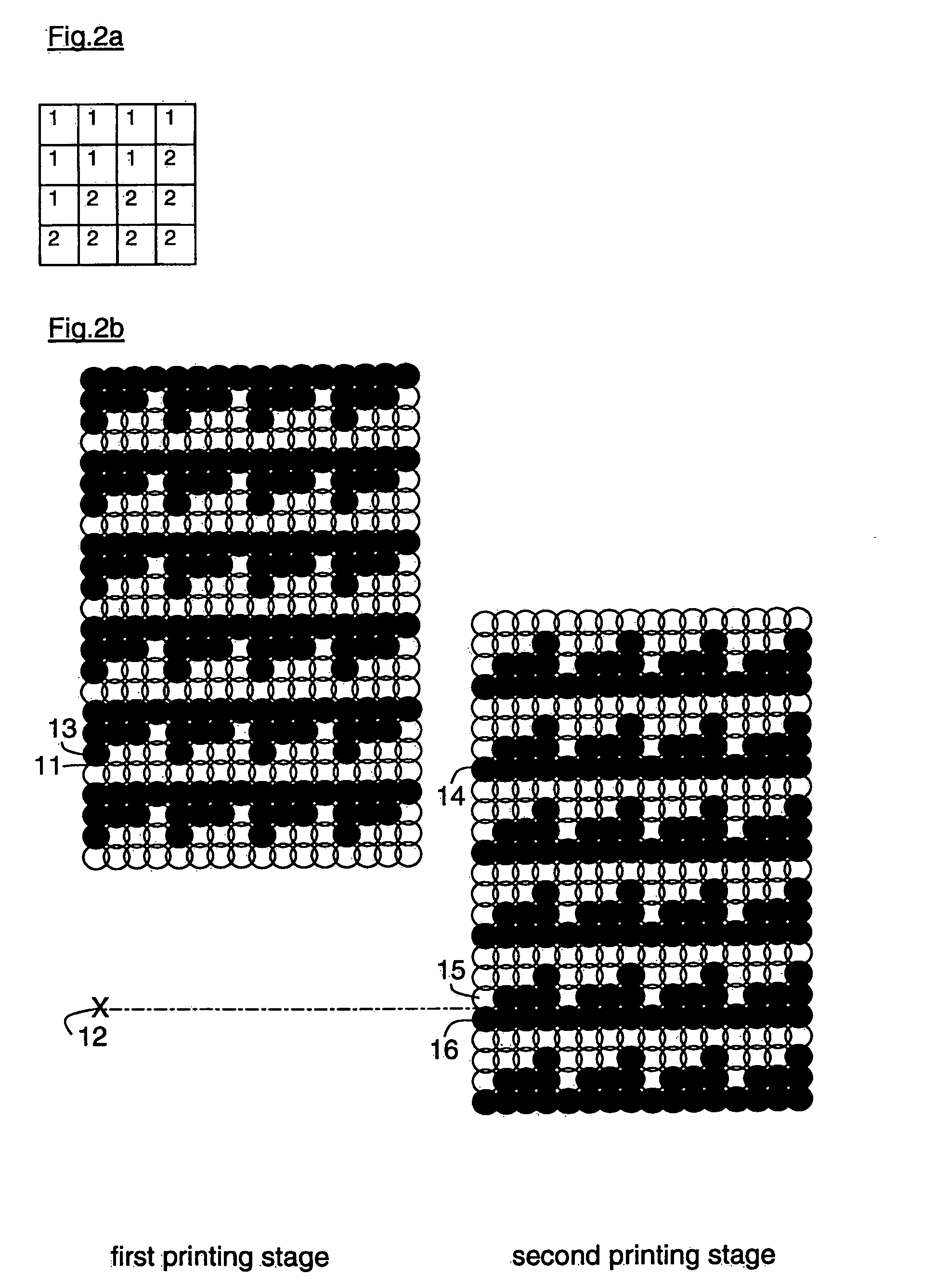
[0035] Suppose the user selects a particular printing mode that enables reproduction of a digital image at a printing resolution of 300 dpi (dots per inch) in both the main scanning and the sub scanning directions. In other words, the printing pitch, i.e. the distance between the centers of two contiguous dots of ink both in the main scanning direction and in the sub scanning direction, is about 85 μm. In this printing mode, the print mask as depicted in FIG. 2a is used. In case the image is a m...

example 2

[0038] A printing device as depicted in FIG. 1 is used to reproduce a digital image. Each print head is provided with 12 discharging elements, i.e. nozzles, arranged in a single linear array, instead of using the print heads 3 provided with four discharging elements as in FIG. 1. The nozzles are positioned equidistant at a resolution of 300 npi (nozzles per inch). This means that the nozzle pitch or element pitch, being the distance between the centers of two adjacent nozzles is about 85 μm.

[0039] Suppose the user selects a particular printing mode that enables reproduction of a digital image at a printing resolution of 900 dpi (dots per inch) in both directions. In other words, the printing pitch, i.e. the distance between the centers of two contiguous dots of ink both in the main scanning direction and in the sub scanning direction, is about 31 μm. To enable rendering of an image with a resolution higher than the nozzle resolution, the print mask associated with the selected prin...


PUM


Abstract

A printing device with at least one bi-directional scanning print head can print images on an image-receiving member in multiple traverses. After each traverse, the image-receiving member is displaced with respect to the print head in the sub scanning direction over a predetermined displacement distance. By selecting for each traverse of the print head an active portion thereof taking account of the displacement step between subsequent traverses, on substantially each position of the image-receiving member, the traversing direction of the print head is the same for each first exposure to an active portion of the traversing print head.

Description

CROSS-REFERENCE TO RELATED APPLICATIONS [0001] This nonprovisional application claims priority under 35 U.S.C. § 119(a) on European Patent Application No. 05100024.8, filed on Jan. 4, 2005, the entirety of which is incorporated herein by reference. BACKGROUND OF THE INVENTION [0002] 1. Field of the Invention [0003] The present invention is related to a printing device such as a printing or copying system employing print heads containing discharging elements, e.g. nozzles, for image-wise forming dots of a marking substance on an image-receiving member, where the marking substance is in fluid form when discharged. Examples of such printing devices are inkjet printers and toner-jet printers. Hereinafter reference will be made to inkjet printers. [0004] 2. Description of Background Art [0005] Print heads employed in inkjet printers and the like usually each contain a plurality of nozzles arranged in (an) array(s). The nozzles usually are placed substantially equidistant. The distance be...

Claims


Application Information

Patent Timeline
IPC IPC(8): B41J29/38
CPCB41J19/147
Inventor REINTEN, HANS
Owner OCE TECH
Why Eureka
Try Eureka