Rectifier unit and rectifier attaching structure

Active Publication Date: 2005-10-11
ORMON CORP
View PDF4 Cites 15 Cited by
  • Summary
  • Abstract
  • Description
  • Claims
  • Application Information

AI Technical Summary

Benefits of technology

[0008]The invention therefore has an object to provide a rectifier unit and a rectifier attaching structure that enable efficient assembly to be achieved, by which plural rectifiers are readily inserted and attached inside the tube through a single insertion operation, and that can address a reduction of the flowmeter in size and a change to the specifications regarding the number of rectifiers to be provided.

Problems solved by technology

With such a rectifier attaching structure, however, a rectifier and a spacer are alternately inserted one by one in the tube from an opening of a lead-in tube of the flow channel to be pushed sequentially to the deepest portion of the lead-in tube, and this insertion operation has to be repeated as many times as the number of components that need to be attached, which makes the job quite troublesome.
In particular, a time needed for the insertion operation is extended as the diameter of the flow channel is reduced with a reduction in size and the rectifiers and the spacers become smaller as well, which lowers the working efficiency and deteriorates the assembling performance.
In addition, there is a limit in reducing the size or the number of components due to the need for a coupler to keep the opening side of the spacers closed.
Further, there is a possibility that a rectifier and a spacer are inserted in a wrong order or skipped by mistake.
In such a case, the rectifiers are not provided at regular intervals, and the originally expected rectifying function cannot be achieved.
Moreover, once the rectifiers are attached inside the lead-in tube, there is no way to confirm whether the rectifiers are attached adequately.
In addition, it is impossible to address a need for a change to the specifications regarding the number of rectifiers to be provided, because no adjustment can be made.
The clearance may possibly cause the leakage of fluid, and it is therefore difficult to add a change to the specifications.

Method used


Image

  • Rectifier unit and rectifier attaching structure
  • Rectifier unit and rectifier attaching structure
  • Rectifier unit and rectifier attaching structure

Examples


Embodiment Construction

[0037]One embodiment of the invention will now be described with reference to the accompanying drawings.

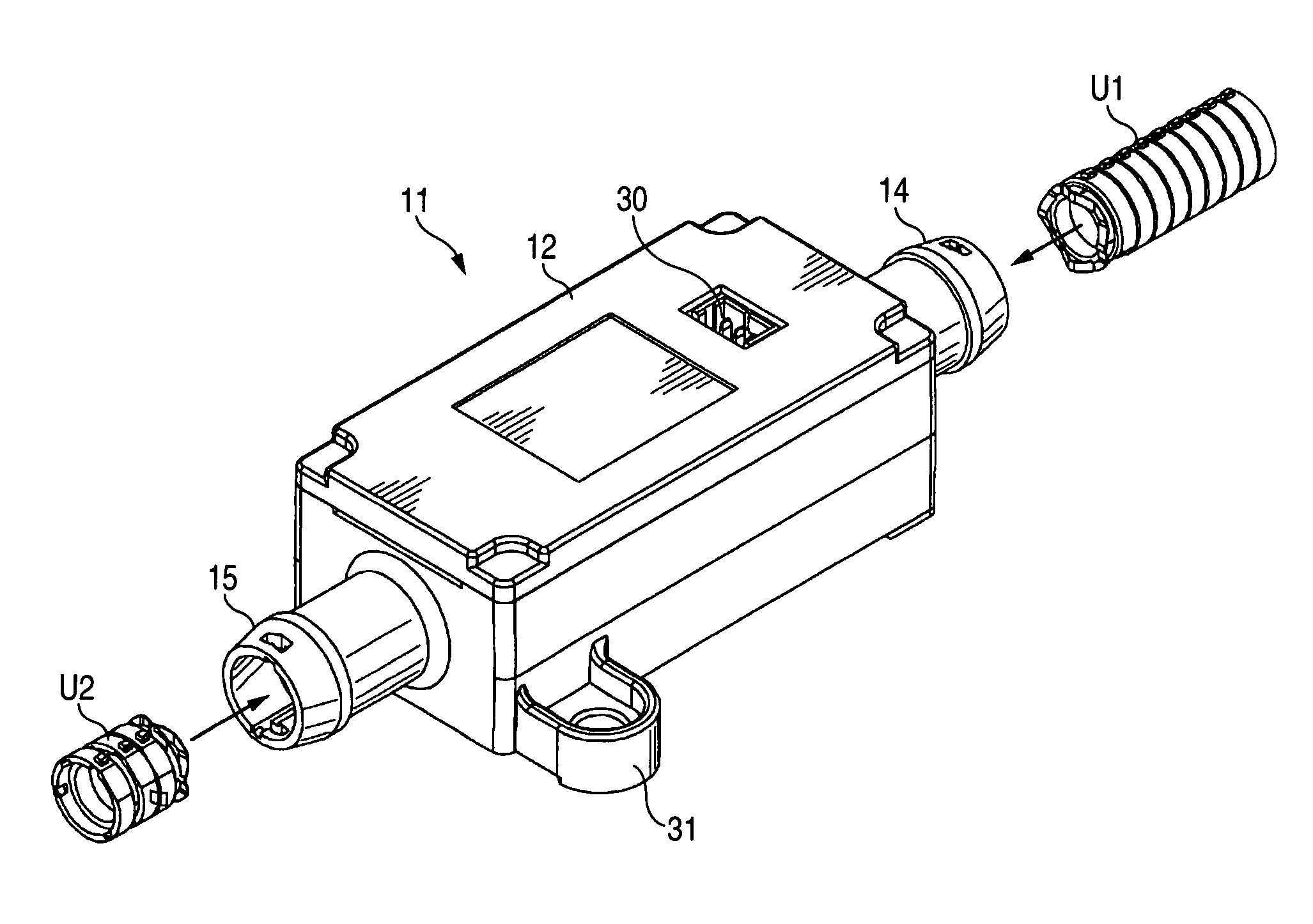
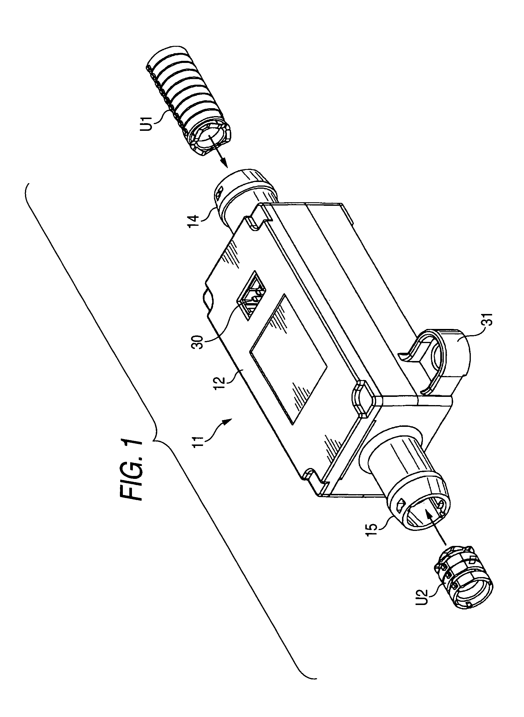
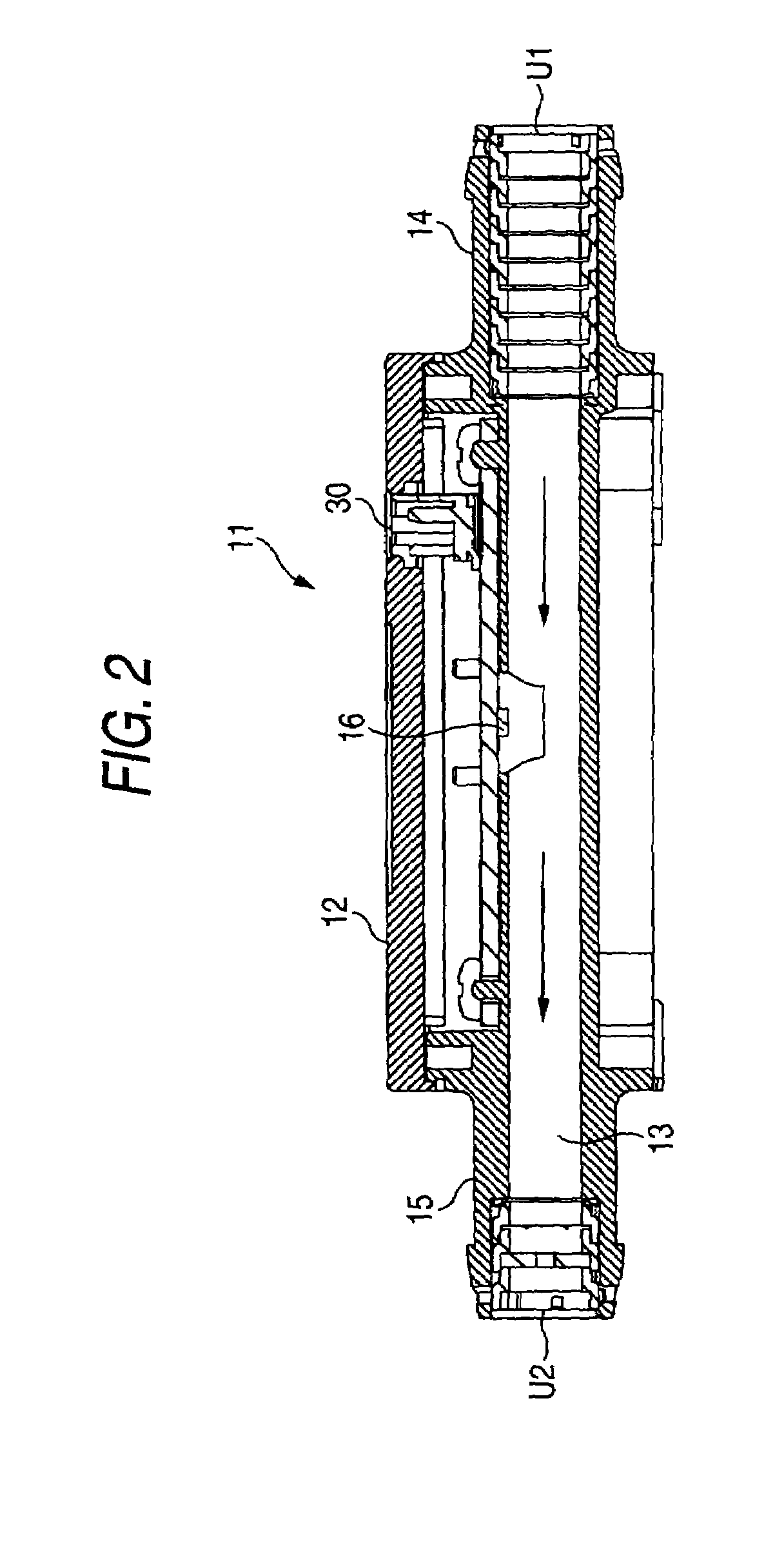
[0038]The accompanying drawings show the attaching structure of rectifier units to be attached to a flowmeter. Referring to FIG. 1 and FIG. 2, a flowmeter 11 includes a flow channel 13 in the shape of a straight tube that transversely penetrates through a rectangular main body 12 in the longitudinal direction. The flowmeter 11 is provided with a lead-in tube 14 protruding forward to serve as an inflow piping portion, at the inflow side of the flow channel 13, and a lead-out tube 15 protruding backward to serve as an outflow piping portion, at the outflow side. A flow sensor 16, serving as a flow rate sensor, is engaged upon the intermediate portion of the flow channel 13 to measure a flow volume of a gas flowing through the flow channel 13.

[0039]A first rectifier unit U1 is attached inside the lead-in tube 14 to make a flow rate distribution homogeneous by eliminating an irregular...


PUM


Abstract

A spacer has an annular concave portion, at one end face, to accept a rectifier that rectifies fluid flowing through a flow channel in a flowmeter, a protruding annular convex portion, at the other end face, of a size to fit in the annular concave portion, and fixing means, on an outer surface, for fixing the spacer to a tube of the flow channel through engagement. A rectifier unit is temporarily assembled by integrating the spacer and the rectifier that are provided alternately in series in an axial direction into a tubular unit. It is thus possible to achieve efficient assembly, by which plural rectifiers are inserted and attached inside the tube through a single insertion operation. Moreover, it is possible to address a need for a reduction of rectifiers in size or a change to the specifications regarding the number of rectifiers to be provided.

Description

BACKGROUND OF THE INVENTION[0001]1. Field of the Invention[0002]The present invention relates to a rectifier unit equipped to a flowmeter that measures a flow volume of fluid, and more particularly to a rectifier unit and a rectifier attaching structure with enhanced rectifier attaching capability.[0003]2. Description of the Related Art[0004]For a rectifier attached to a flowmeter, as is shown in FIG. 12, a flow sensor 124 serving as a flow rate sensor is generally attached to an intermediate portion of a flow channel 123 defined to transversely penetrate through a main body 122 of a flowmeter 121. The flow sensor 124 measures a flow rate produced within the flow channel with the use of a flow chip, and outputs the measurement result in the form of a voltage, on the basis of which a flow volume is measured.[0005]Incidentally, in order to stabilize the measuring ability of the flow sensor 124, rectifiers 125, such as rectifier wire meshes, each rectifying fluid flowing from the upstr...

Claims


Application Information

Patent Timeline
IPC IPC(8): G01F1/684G01F1/00G01F1/05G01F15/00G01F1/68F15D1/00
CPCF15D1/001G01F1/684G01F15/00
Inventor NOZOE, SATOSHIFUJIWARA, TOSHIMITSUKURIBAYASHI, HIDENARIMAKINO, OSAMUMORISAWA, TATSUHIDE
Owner ORMON CORP
Why Eureka
Try Eureka