Exhaust device of engine
- Summary
- Abstract
- Description
- Claims
- Application Information
AI Technical Summary
Benefits of technology
Problems solved by technology
Method used
Image

Examples
embodiment 1
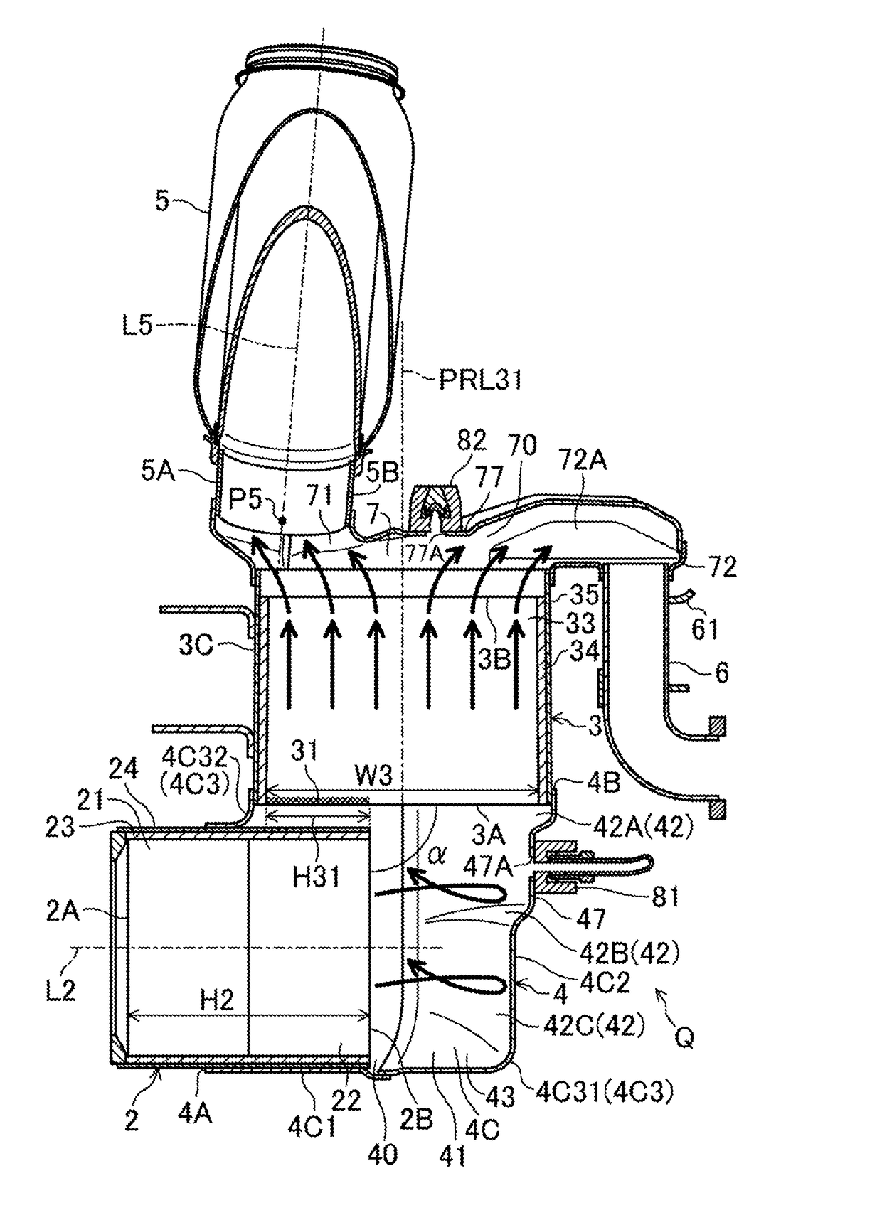
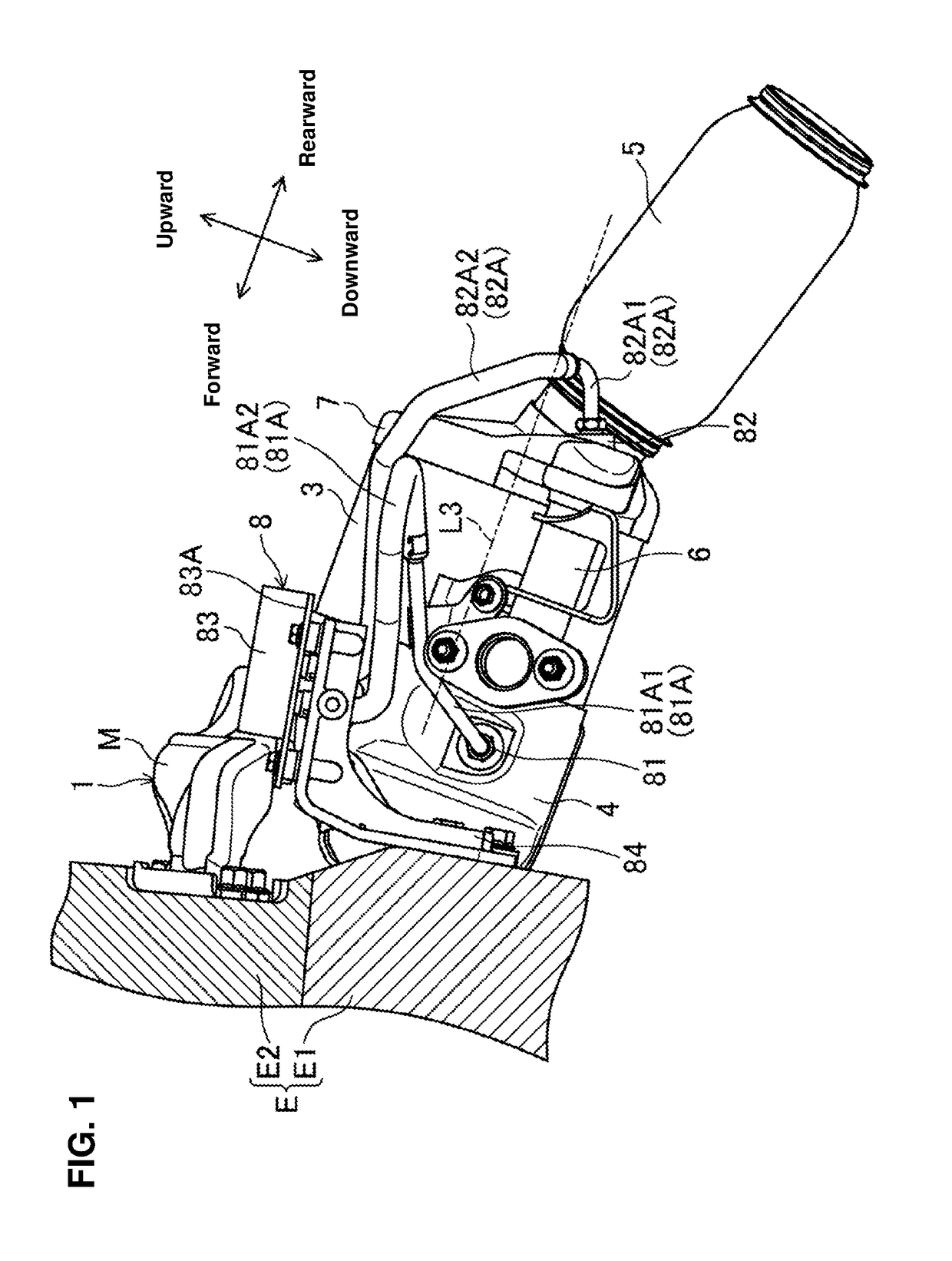
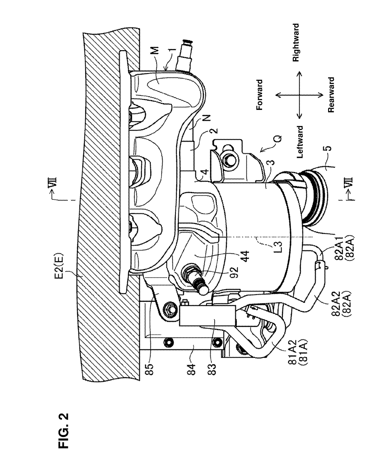
[0031]
[0032]An engine, to which an exhaust device 1 according to a first embodiment is applied, is an in-line four-cylinder gasoline engine (in-line multi-cylinder engine) which is installed to an automotive vehicle. The engine is disposed laterally at a front portion of a FF vehicle.
[0033]Herein, the present invention is applicable not only to this four-cylinder gasoline engine but to any other multi-cylinder engine or a diesel engine. Further, the present exhaust device 1 is applicable not only to the FF vehicle but to any other layout-type vehicles, such as a RR vehicle or a 4WD vehicle, including a motorcycle.
[0034]The engine has an engine body E which comprises a cylinder block E1 and a cylinder head E2 as shown in FIG. 1. While detailed illustrations are omitted here, first through fourth cylinders which are formed by the cylinder block E1 and the cylinder head E2 are arranged in line in a direction vertical to a paper surface. A combustion chamber of each cylinder is formed b...
PUM
 Abstract
Description
Claims
Application Information
 - R&D
- Intellectual Property
- Life Sciences
- Materials
- Tech Scout
- Unparalleled Data Quality
- Higher Quality Content
- 60% Fewer Hallucinations
Browse by: Latest US Patents, China's latest patents, Technical Efficacy Thesaurus, Application Domain, Technology Topic, Popular Technical Reports.
© 2025 PatSnap. All rights reserved.Legal|Privacy policy|Modern Slavery Act Transparency Statement|Sitemap|About US| Contact US: help@patsnap.com