R-T-B system permanent magnet and plating film

a permanent magnet and plating film technology, applied in the field of r-t-b system permanent magnets, can solve the problems of poor corrosion resistance of such magnets, difficult to freely set the amount of s contained difficult control of the s content in the plating film, so as to improve the adhesion to the magnet base body, improve the hardness of the plating film, and improve the effect of hardness

Inactive Publication Date: 2006-06-29
TDK CORPARATION
View PDF12 Cites 5 Cited by
  • Summary
  • Abstract
  • Description
  • Claims
  • Application Information

AI Technical Summary

Benefits of technology

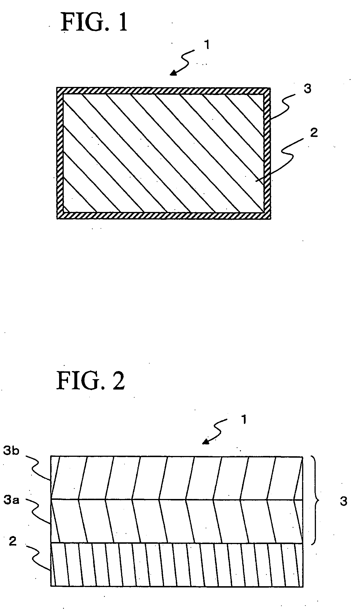
[0011] The present inventors have confirmed that C (carbon) is an element whose content in a plating film can be easily controlled to improve corrosion resistance of the film and which is effective for improving the hardness of a plating film. The present inventors further found that by incorporating a certain amount of C in a plating film, plating film adhesion could be improved. That is, the present invention is directed to an R—T—B system permanent magnet comprising a magnet base body and a plating layer which covers the magnet base body surface and which comprises, when C content is defined as Cc, 0.005<Cc≦0.2 wt. %. The magnet base body is constituted from a sintered body which comprises at least main phase grains consisting of an R2T14B compound, and a grain boundary phase which comprises a larger amount of R than the main phase grains. In the present invention, R represents one or more rare earth elements including Y, and T represents one or more transition metal elements comprising Fe, or Fe and Co as essential components.
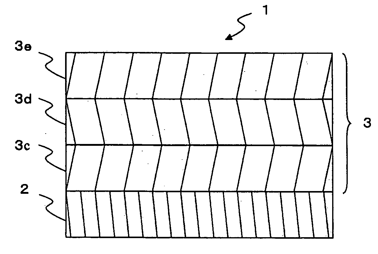
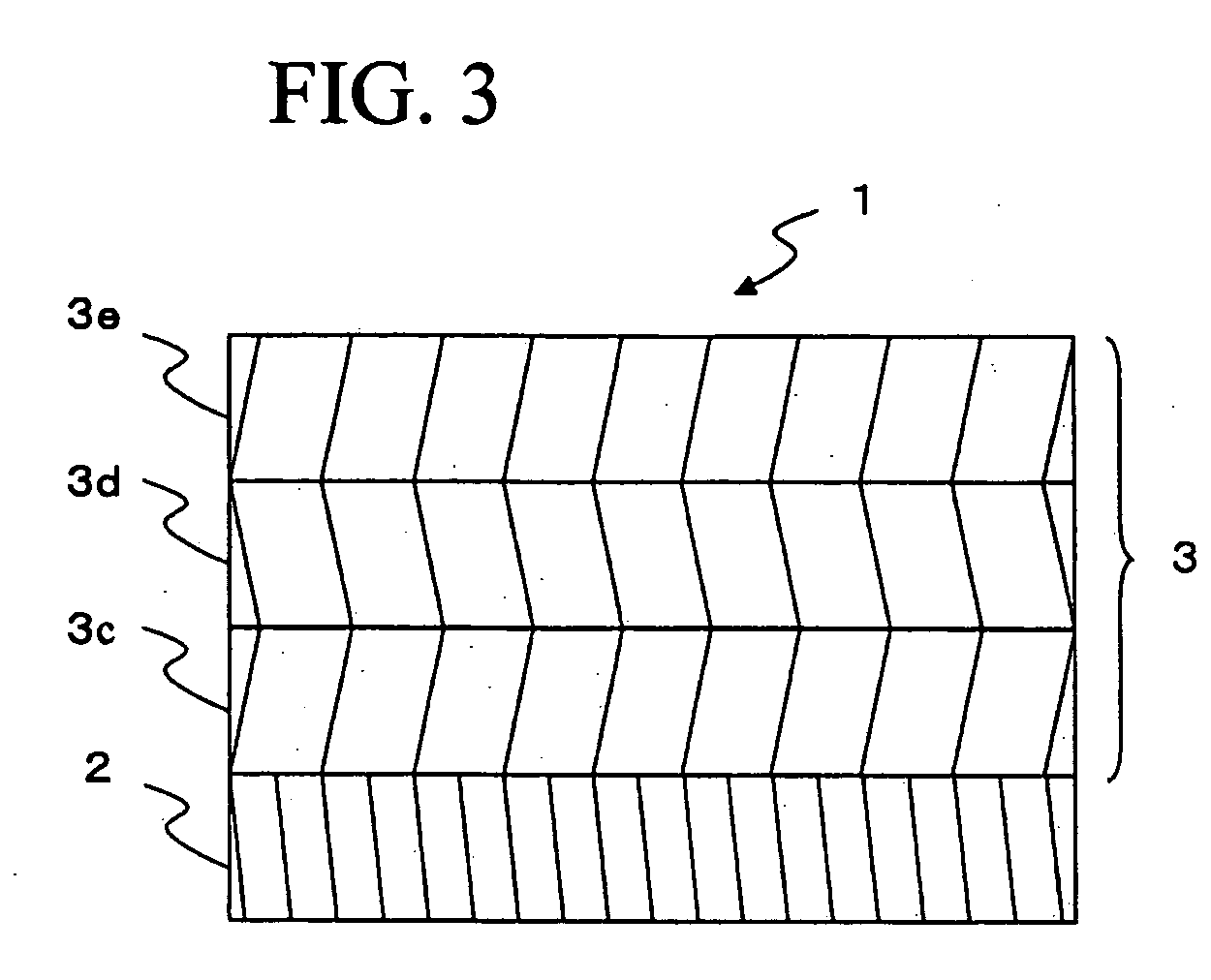
[0013] In some cases, the plating film of the R—T—B system permanent magnet is constituted from a plurality of plating layers. In such a case, the present inventors discovered that the difference in C content between the respective layers has an effect on corrosion resistance. That is, when the plating film comprises a first plating layer provided on a magnet base body surface side and a second plating layer provided on the first plating layer, it is effective for improving corrosion resistance to set the difference in C content between the first plating layer and the second plating layer to be 0.1 wt. % or less. The first plating layer and the second plating layer are preferably electrolytic plating of Ni and / or Cu.
[0015] According to the present invention, plating film corrosion resistance can be secured by using C, whose content can be easily controlled, in the plating film. Further, incorporating a certain amount of C in the plating film improves the hardness of the plating film and improves adhesion to the magnet base body. In particular, as in the present invention, such effects are remarkable as a result of providing the plating film with a plurality of layers having different C content.

Problems solved by technology

Even for R—T—B system permanent magnets which have excellent magnetic properties, some technical problems exist.
That is, the main constituents of an R—T—B system permanent magnet are R and Fe, which are susceptible to oxidation, so that the corrosion resistance of such a magnet is poor.
However, investigations carried out by the present inventors showed that it is not easy to control S content in a plating film.
However, it is difficult to freely set the amount of S contained in the plating film if the type of brightener is specified.
Therefore, it must be said that a method to improve corrosion resistance by controlling the S content in the plating film is not very versatile for producing an actual R—T—B system permanent magnet.
However, no effective methods have yet been proposed for improving the hardness of a plating film.

Method used


Image

  • R-T-B system permanent magnet and plating film
  • R-T-B system permanent magnet and plating film
  • R-T-B system permanent magnet and plating film

Examples


example 1

[0079] A strip-shaped alloy having a certain composition was manufactured by a strip casting method. This strip-shaped alloy was made to occlude hydrogen at room temperature. The temperature was raised to about 400 to 700° C. in an Ar atmosphere, and a coarse powder was obtained by dehydrogenation.

[0080] This coarse powder was subjected to pulverizing using a jet mill. The pulverizing was conducted by purging the jet mill interior with N2 gas and then using a high-pressure N2 gas flow. The mean particle size of the obtained fine powder was 4.0 μm. It is noted that prior to carrying out the pulverizing, 0.01 to 0.10 wt. % of zinc stearate was added as a milling aid.

[0081] The obtained fine powder was compacted in a 1,200 kA / m (15 kOe) magnetic field at a pressure of 98 MPa (1.0 ton / cm2), to thereby yield a compacted body. This compacted body was sintered in a vacuum for 4 hours at 1,030° C., and then quenched. The obtained sintered body was subsequently subjected to a two-stage agi...

example 2

[0092] In this example, Cu plating was examined in the same manner as the Example 1.

[0093] Using samples consisting of the same R—T—B system permanent magnet as in Example 1, plating films were formed under the conditions illustrated in FIG. 7. As shown in FIG. 7, sample Nos. 8 to 12 were prepared by varying the plating bath composition or current density. Once the plating films were formed, they were evaluated in the same manner as in Example 1. The results are shown in FIG. 7. Based on these results, the relationship between current density and C content, the relationship between C content and plating film hardness, and the relationship between C content and plating film adhesion were found. Those results are given in FIGS. 8 and 9.

[0094] From FIGS. 7 to 9, it was confirmed that plating film hardness increases as the plating film C content increases even for Cu plating, and that adhesion also improves. For a Cu plating, a preferable C content is between 0.006 and 0.05 wt. %.

example 3

[0095] Using samples consisting of the same R—T—B system permanent magnet as in Example 1, Ni plating films were formed under the conditions illustrated in FIG. 10. Sample Nos. a and b were monolayer Ni plating, and sample Nos. c to h were multi-layer (bilayer) Ni plating. In addition, for sample Nos. c to e, the C content in the first plating layer and the second plating layer was varied by adjusting the deposition conditions of the first and second plating layers. Further, for sample Nos. f to h, the C content in the second plating layer was varied by adjusting the current density of the second plating layer.

[0096] Once Ni plating had been completed, the formed plating films were evaluated in the same manner as in Example 1. Plating film composition analysis was carried out for sample Nos. c to h (bilayer plating) using monolayer samples whose first plating layer had been plated on a sample (magnet base body) consisting of a sintered body under the same conditions as the first pl...


PUM

PropertyMeasurementUnit
Contentaaaaaaaaaa
Hardnessaaaaaaaaaa
Corrosion resistanceaaaaaaaaaa

Abstract

It is an object of the present invention to provide an R—T—B system permanent magnet which is easy to apply in the production of an actual R—T—B system permanent magnet, and which contains a plating film that is also effective in securing hardness. The present invention achieves this object by providing an R—T—B system permanent magnet 1 which contains a magnet base body 2 constituted from a sintered body which contains at least main phase grains containing an R2T14B compound, and a grain boundary phase which contains a larger amount of R than the main phase grains, and a plating film 3 which covers the magnet base body 2 surface and which contains, when C content is defined as Cc (wt. %), 0.005<Cc≦0.2 wt. %.

Description

BACKGROUND OF THE INVENTION [0001] 1. Field of the Invention [0002] The present invention relates to an R—T—B system permanent magnet formed with a plating film on its surface, and a plating film. [0003] 2. Description of the Related Art [0004] R—T—B system permanent magnets which have a main phase of an R2T14B type intermetallic compound have excellent magnetic properties. Further, their main composition is Nd, which is abundant as a natural resource and is relatively inexpensive. These factors mean that R—T—B system permanent magnets are used in a variety of electric devices. Herein, R represents one or more rare earth elements, which includes Y, and T represents one or more transition metal elements essentially comprising Fe, or Fe and Co. [0005] Even for R—T—B system permanent magnets which have excellent magnetic properties, some technical problems exist. One of these is corrosion resistance. That is, the main constituents of an R—T—B system permanent magnet are R and Fe, which...

Claims


Application Information

Patent Timeline
IPC IPC(8): B32B15/04B32B15/00B32B15/01B32B19/00B32B9/04
CPCC23C18/08C25D3/12C25D3/38C25D5/12Y10T428/12861H01F41/026C25D7/001Y10T428/12944Y10T428/12576H01F1/0577Y10T428/31678
Inventor NAKAYAMA, YASUYUKIYAMASAWA, KAZUHITO
Owner TDK CORPARATION
Why Eureka
Try Eureka