
Information recording medium and manufacturing method thereof

a technology of information recording medium and manufacturing method, which is applied in the field of information recording medium, can solve the problems of reducing the crystallization speed of the recording layer

Inactive Publication Date: 2006-06-29
PANASONIC CORP
View PDF5 Cites 20 Cited by
  • Summary
  • Abstract
  • Description
  • Claims
  • Application Information

AI Technical Summary

Benefits of technology

[0008] Consequently, crystallization in the amorphous phase corresponding to recorded information is allowed to progress by reproducing light, with the result that the amplitude of the reproducing signal is reduced to cause degradation in the reproducing signal quality.
[0011] In order to achieve the above-mentioned objectives, an information recording medium of the present invention in which its recording layer can phase-change reversibly between a crystal phase and an amorphous phase by using an optical means or an electric means is provided with a recording layer that contains at least Ge, Te, M1 (which is at least one element selected from the group consisting of Sc, Y, La, Ce, Pr, Nd, Sm, Gd, Tb, Dy, Ho, Er, Yb and Lu (the same is true for the following description)), M2 (which is at least one element selected from the group consisting of Sb and Bi (the same is true for the following description)) and M3 (which is at least one element selected from the group consisting of Te and Bi (the same is true for the following description)). This information recording medium, which allows the recording layer to have a high melting point and a high crystallizing temperature, provides superior thermal stability, and also prevents degradation in reproducing light.
[0013] In the information recording medium, the recording layer contains at least GeTe, M22Te3 and M1M3 (which is a compound containing M1 and M3 at a virtually equal rate), or may contain a material represented by GeTe-M1M3-M22Te3. With this structure, by the use of M1M3 that is a stoichiometric composition compound having a high melting point, the recording layer is allowed to have a high melting point and a high crystallizing temperature so that it is possible to provide an information recording medium which has a high crystallization speed with superior thermal stability, and prevents degradation in reproducing light.
[0014] In the information recording medium, with respect to the material for the recording layer, one portion of GeTe may be substituted by M1M3 (in which M3 is at least one element selected from the group consisting of Te and Bi), and represented by (GeTe-M1M3)-M22Te3. In accordance with this information recording medium, M1 by which Ge in the Ge-M2—Te3 three-element composition is substituted makes it possible to raise the crystallizing temperature of the recording layer so that an information recording medium which has superior thermal stability, and prevents degradation in reproducing light can be obtained. Since GeTe and M1M3 are the same NaCl-type compounds in the crystal structure, there is no change in the crystallizing process of the recording layer even when Ge is substituted by M1.
[0015] In the above-mentioned information recording medium, the recording layer may further contain M2, and may be represented by GeTe-M1M3-M22Te3-M2. With this structure, when Bi is used as M2, the crystallizing property of the recording layer is improved to make the spot diameter of a laser beam smaller so that an information recording medium which can form stable recording marks even in the case of a short laser irradiation time is achieved. When Sb is used as M2, an excessive amount of Sb is added to the material represented by GeTe-M1M3-M22Te3, so that the excessive amount of Sb can adjust the crystallization speed depending on the amount of addition, thereby making it possible to improve the crystallizing temperature to enhance the thermal stability of recording marks, and also to suppress a substance transfer upon repetitive recording operations.

Problems solved by technology

However, in the case when the thickness of the recording layer is made thinner, since it becomes difficult to move atoms, the crystallization speed of the recording layer is reduced.

Method used


Image

  • Information recording medium and manufacturing method thereof
  • Information recording medium and manufacturing method thereof
  • Information recording medium and manufacturing method thereof

Examples


embodiment 1

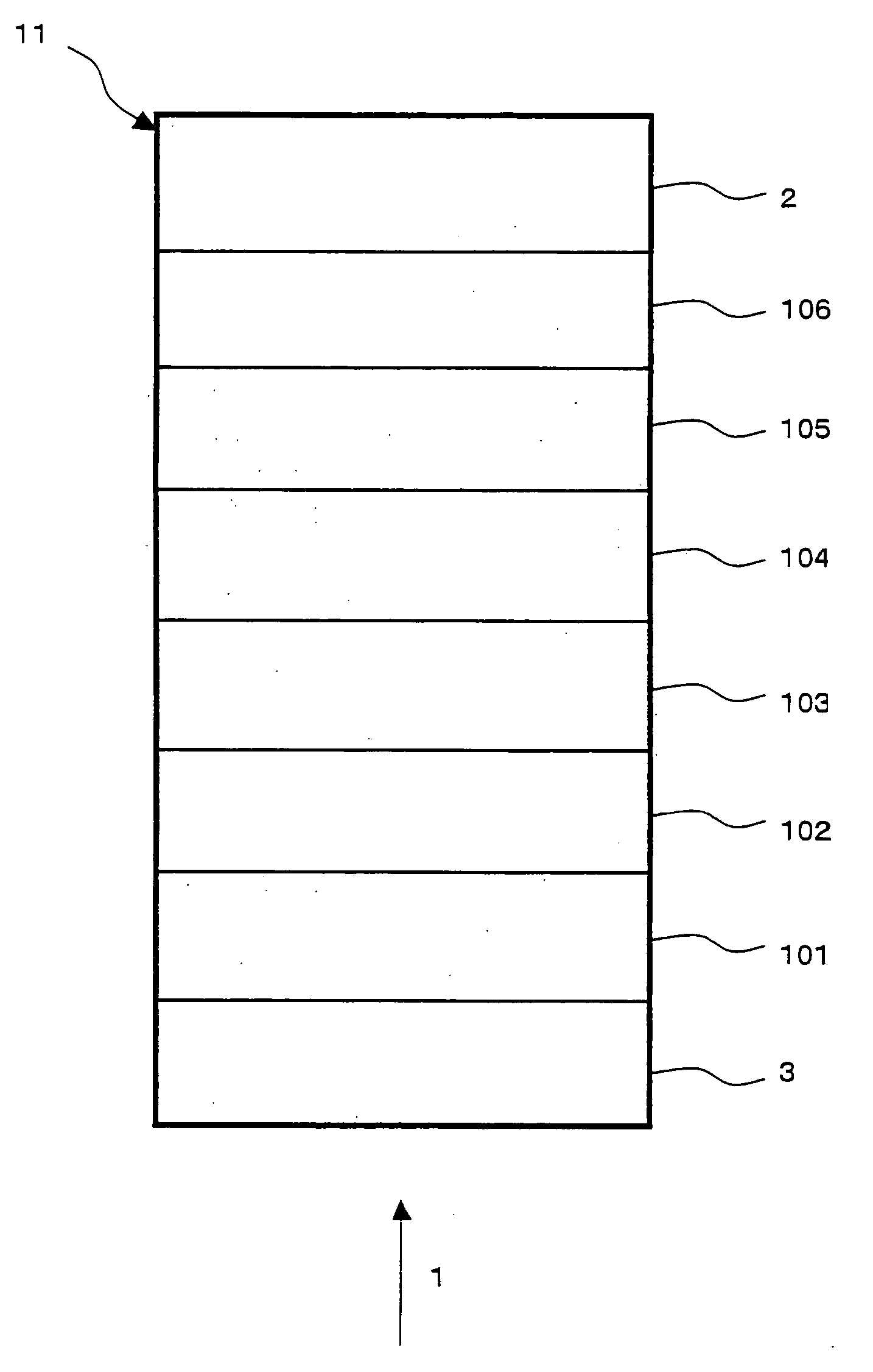
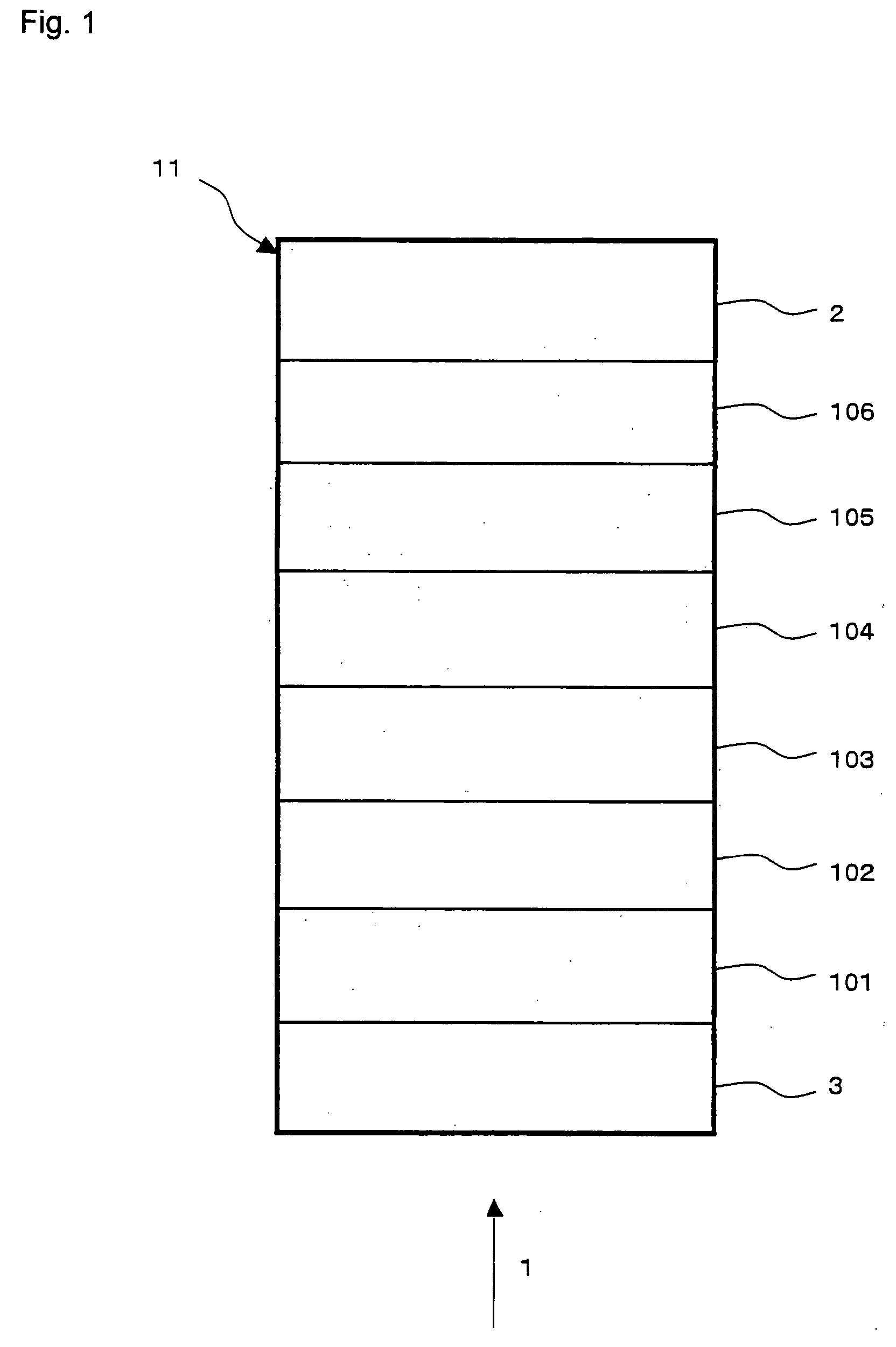
[0056] Embodiment 1 explains one example of an information recording medium of the present invention. FIG. 1 shows a partial cross-sectional view of an information recording medium 11 of Embodiment 1. This information recording medium 11 is an optical information recording medium that is capable of recording and reproducing information through irradiation with a laser beam 1.

[0057] The information recording medium 11 is constituted by a reflective layer 106, a second dielectric layer 105, a second interface layer 104, a recording layer 103, a first interface layer 102, a first dielectric layer 101 and a transparent layer 3 that are successively laminated on a substrate 2.

[0058] Since the laser beam 1 is made incident on the side of a transparent layer 3 and light reflected from the recording layer 103 is utilized as a reproducing signal, the transparent layer 3, placed on the light incident side of the recording layer 103, is preferably made to have little light absorbing property...

embodiment 2

[0097] Embodiment 2 explains one example of an information recording medium of the present invention. FIG. 4 shows a partial cross-sectional view of an information recording medium 14 of Embodiment 2. This information recording medium 14 is a multilayer optical information recording medium that is capable of recording and reproducing information through irradiation of a laser beam 1 from one side of the faces.

[0098] The information recording medium 14 is constituted by N sets (N is a natural number satisfying N≧2) of layers, that is, the N information layer 36, the (N−1) information layer 34, the first information layer 31 and the transparent layer 3, which are successively laminated on the substrate 2 through optical separation layers 35, 33, 32, etc. Those information layers up to the (N−1)-numbered layer counted from the light incident side of the laser beam 1 and those information layers from the first information layer 31 to the (N−1) information layer 34 (hereinafter, the N-n...

embodiment 3

[0137] Embodiment 3 explains one example of an information recording medium in which, N=2 holds in the multilayer optical information recording medium of Embodiment 2 in the present invention, that is, a structure in which the information recording medium is constituted by two sets of information layers. FIG. 7 shows one portion of a cross-sectional view of the information recording medium 17 of Embodiment 3. The information recording medium 17 is a two-layered optical information recording medium 14 that is capable of recording and reproducing information through irradiation of a laser beam 1 from one side of the faces.

[0138] The information recording medium 17 is constituted by a second information layer 41, an optical separation layer 32, a first information layer 31 and a transparent layer 3 that are successively laminated on the substrate 2. With respect to the substrate 2, the optical separation layer 32, the first information layer 31 and the transparent layer 3, the same ma...


PUM


Abstract

An information recording medium, comprising: a recording layer which can phase-change reversibly between a crystal phase and an amorphous phase by using an optical means or an electric means, wherein the recording layer comprises at least Ge, Te, M1 (which is at least one element selected from the group consisting of Sc, Y, La, Ce, Pr, Nd, Sm, Gd, Tb, Dy, Ho, Er, Yb and Lu), M2 (which is at least one element selected from the group consisting of Sb and Bi) and M3 (which is at least one element selected from the group consisting of Te and Bi).

Description

FIELD OF THE INVENTION [0001] The present invention relates to an information recording medium on and from which information is recorded, erased, rewritten and reproduced optically or electrically and a method for manufacturing such an information recording medium. BACKGROUND OF THE INVENTION [0002] Information recording media include a phase-change optical information recording medium on and from which information is recorded, erased, rewritten and reproduced optically by using a laser beam. Upon recording, erasing and rewriting information on and from the phase-change optical information recording medium, a phenomenon in which the recording layer can phase-change reversibly between a crystal phase and an amorphous phase is utilized. In general, upon recording information, a high-power (recording power) laser beam is applied to the recording layer to heat the recording layer to a temperature higher than its melting point; thus, the irradiated portion is fused and then rapidly coole...

Claims


Application Information

Patent Timeline
IPC IPC(8): B32B3/02G11B7/24038G11B7/243G11B7/26H01L45/00
CPCG11B7/24038G11B7/243G11B7/266G11B2007/24312G11B2007/24316Y10T428/21H01L45/1233H01L45/144H01L45/1625H01L27/2463H01L45/06H10B63/80H10N70/231H10N70/826H10N70/8828H10N70/026G11B7/241
Inventor SUENAGA, TAEKO
Owner PANASONIC CORP
Learn More