Method for manufacturing magnetic recording medium

Inactive Publication Date: 2006-06-15
TDK CORPARATION
View PDF13 Cites 55 Cited by
  • Summary
  • Abstract
  • Description
  • Claims
  • Application Information

AI Technical Summary

Benefits of technology

[0011] According to various exemplary embodiments of this invention, after a filling material is deposited on an object to be processed in which a temporary underlying material is deposited on convex portions of a recording layer to fill concave portions, an excess part of the filling material is removed by dry etching that tends to selectively remove a convex portion faster than a concave portion. Thus, it is possible to efficiently remove the filling material covering side faces of the temporary underlying material. Moreover, when an etching method in which an etching rate of the temporary underlying material is higher than that of the filling material is used, the temporary underlying material can be selectively removed and a surface can be flattened.
[0012] The etching method for selectively removing the temporary underlying material is preferably dry etching using reactive gas having a property of chemically reacting with the temporary underlying material to remove the temporary underlying material. Production efficiency can be largely improved by performing both removal of the excess part of the filling material and flattening (removal of the temporary underlying material) by dry etching, as compared with a case of using a dry process and a wet process together.
[0013] Alternatively, the excess part of the filling material and the temporary underlying material may be removed in one step by using dry etching in which the etching rate of the temporary underlying material is higher than that of the filling material. Flattening the surface in one step in that manner can further improve the production efficiency.
[0018] On the other hand, suppose that an object to be processed in which the concave portions are filled with the filling material and the convex portions are formed by the temporary underlying material is prepared, and that the temporary underlying material is removed by dry etching in which the etching rate of the temporary underlying material is higher than that of the filling material forming the concave portions. In this case, it is possible to remove all the convex portions formed by the temporary underlying material in a short time irrespective of the widths of the convex portions, while the processing of the concave portions is suppressed. Therefore, it is possible to prevent generation of the difference of the surface roughness and formation of the step in the surface.

Problems solved by technology

However, many problems including the limitation of the magnetic head processing, improper recording of information onto a track adjacent to a target track and crosstalk that are caused by broadening of a magnetic field, and the like have been made apparent.
Thus, the improvement of the areal density by the conventional development approach has reached the limit.
On the other hand, a magnetic recording medium such as a hard disk has a problem that a flying height of a head slider is unstable in a case where concavity and convexity of a surface is large.
In this case, the surface of the recording layer is not flattened sufficiently.
If the resist layer is formed to be excessively thick, formation of the projection can be suppressed because it is difficult for the filling material to be deposited around the base of the side face of the resist layer.
However, the excessively thick resist layer may cause easy destruction of the convex portion of the resist layer that is processed to have a concavo-convex pattern by exposure and development or may lower processing accuracy of the recording layer.

Method used


Image

  • Method for manufacturing magnetic recording medium
  • Method for manufacturing magnetic recording medium
  • Method for manufacturing magnetic recording medium

Examples


Embodiment Construction

[0047] Preferred exemplary embodiments of the present invention are now described with reference to the drawings.

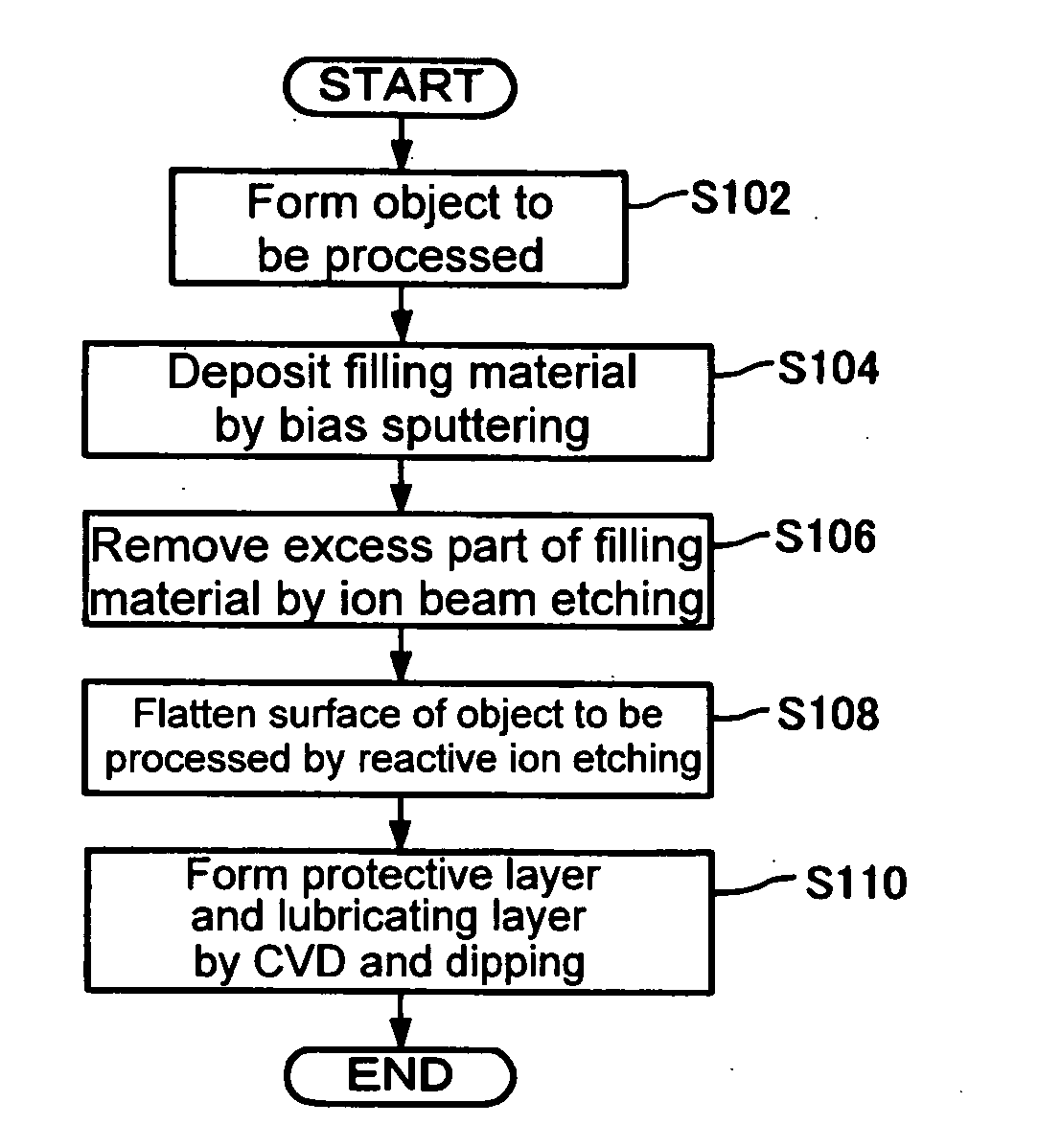
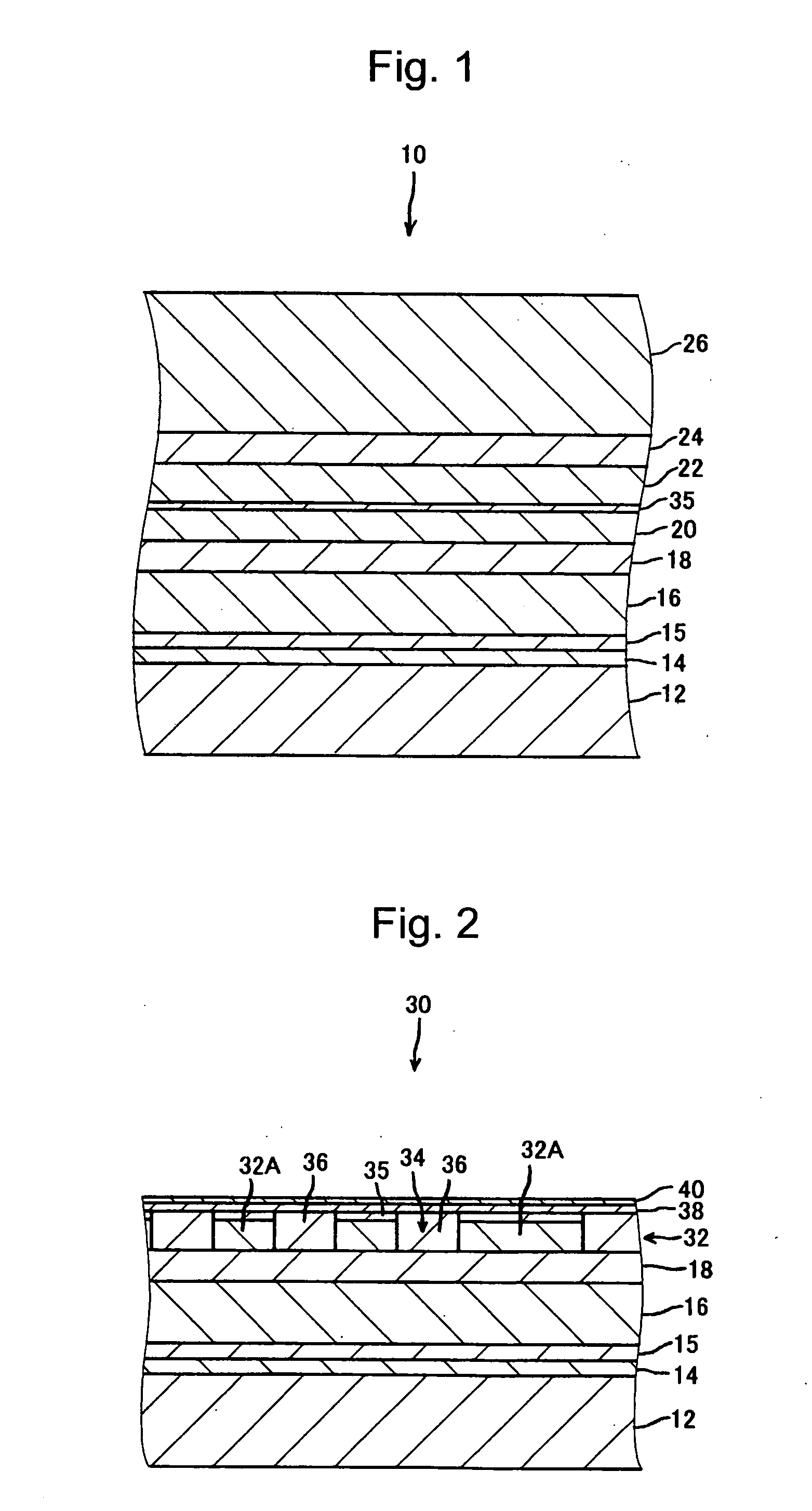
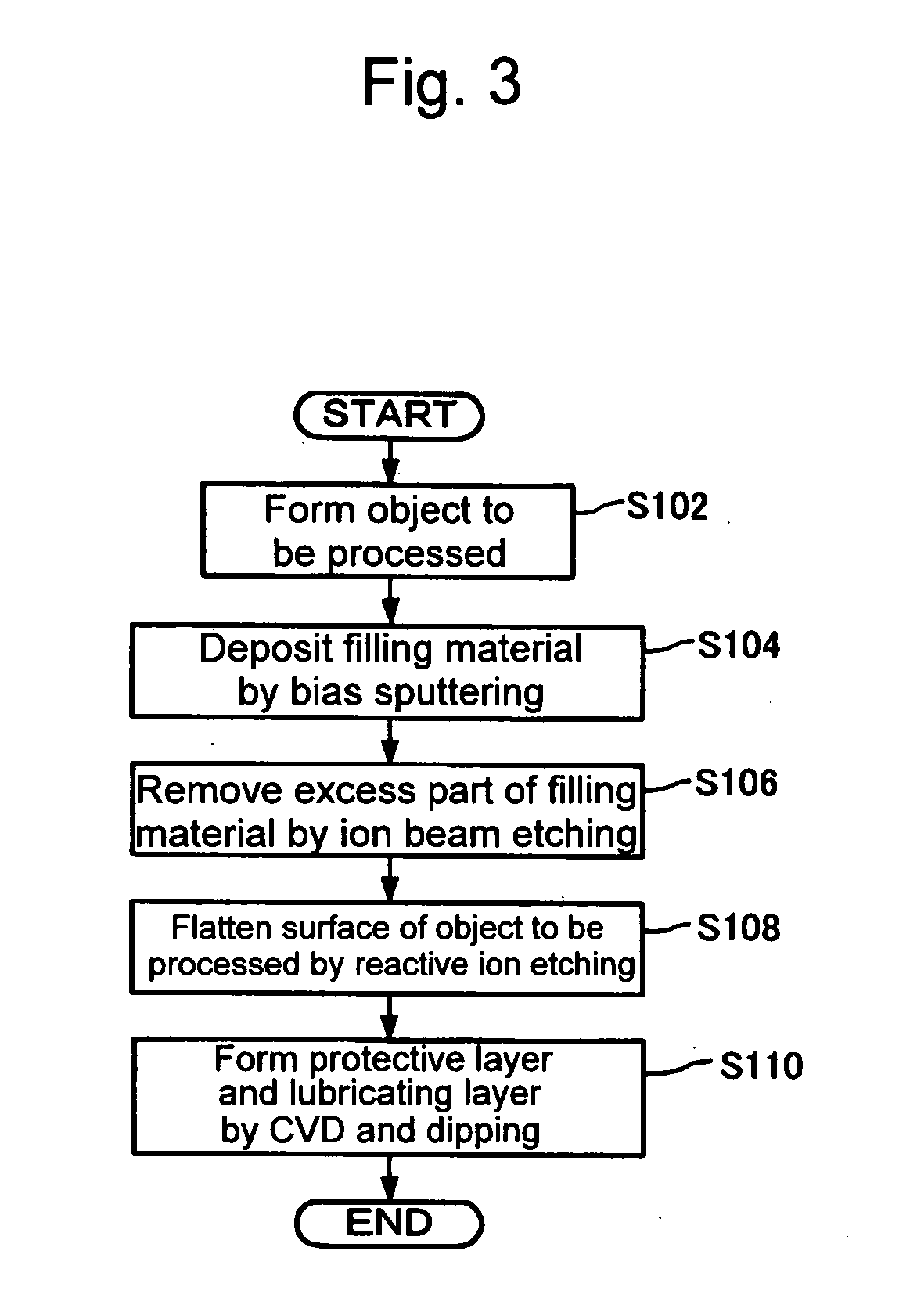
[0048] A first exemplary embodiment of the present invention relates to a method for manufacturing a magnetic recording medium 30. The method includes: processing a starting body of an object to be processed 10 shown in FIG. 1, in which a continuous recording layer 20 and other layers are formed over a substrate 12, so as to divide the continuous recording layer 20 into a number of recording elements 32A (convex portions of a recording layer), as shown in FIG. 2, and form the recording layer 32 having a predetermined concavo-convex pattern; and filling concave portions 34 between the recording elements 32A (concave portions of the concavo-convex pattern) with a filling material 36 to flatten a surface. The manufacturing method of the first exemplary embodiment has a feature in a filling material removing step of removing an excess part of the filling material 36 and a fl...


PUM

PropertyMeasurementUnit
Angleaaaaaaaaaa
Angleaaaaaaaaaa

Abstract

A method for manufacturing a magnetic recording medium is provided, which can manufacture a magnetic recording medium that includes a recording layer having a concavo-convex pattern and has a sufficiently flat surface. The method includes the steps of: forming an object to be processed including a recording layer having a predetermined concavo-convex pattern formed over a substrate and a first mask layer (temporary underlying material) formed at least on recording elements (convex portions) of the recording layer; depositing a filling material on the object to be processed to fill concave portions; removing a part of the filling material by dry etching to expose at least side faces of the first mask layer; and removing the first mask layer by an etching method in which an etching rate of the first mask layer is higher than that of the filling material to flatten a surface.

Description

BACKGROUND OF THE INVENTION [0001] 1. Field of the Invention [0002] The present invention relates to a manufacturing method of a magnetic recording medium including a recording layer having a concavo-convex pattern. [0003] 2. Description of the Related Art [0004] Conventionally, in a magnetic recording medium such as a hard disk, various types of development such as miniaturization of magnetic particles forming a recording layer, change of a material, and finer head processing have been made to largely improve areal density of the recording layer. The improvement of the areal density is expected to continue. However, many problems including the limitation of the magnetic head processing, improper recording of information onto a track adjacent to a target track and crosstalk that are caused by broadening of a magnetic field, and the like have been made apparent. Thus, the improvement of the areal density by the conventional development approach has reached the limit. [0005] Therefore...

Claims


Application Information

Patent Timeline
IPC IPC(8): B05D5/12C23C14/32B05D1/40B44C1/22C23C14/00C23F1/00B05D3/00
CPCB82Y10/00C23F4/00G11B5/74G11B5/743G11B5/82G11B5/855
Inventor SUWA, TAKAHIROOKAWA, SHUICHISHIMAKAWA, KAZUYA
Owner TDK CORPARATION
Why Eureka
Try Eureka