Apparatus and methods for ion beam implantation
a technology of ion beam and apparatus, which is applied in the field of apparatus for ion beam implantation, can solve the problems of ensuring a ribbon beam and detectable stripes of varying ion beam dose in the workpiece, and achieves the effects of simple beamline, high resolving power, and efficient mass analysis
- Summary
- Abstract
- Description
- Claims
- Application Information
AI Technical Summary
Benefits of technology
Problems solved by technology
Method used
Image
Examples
first embodiment
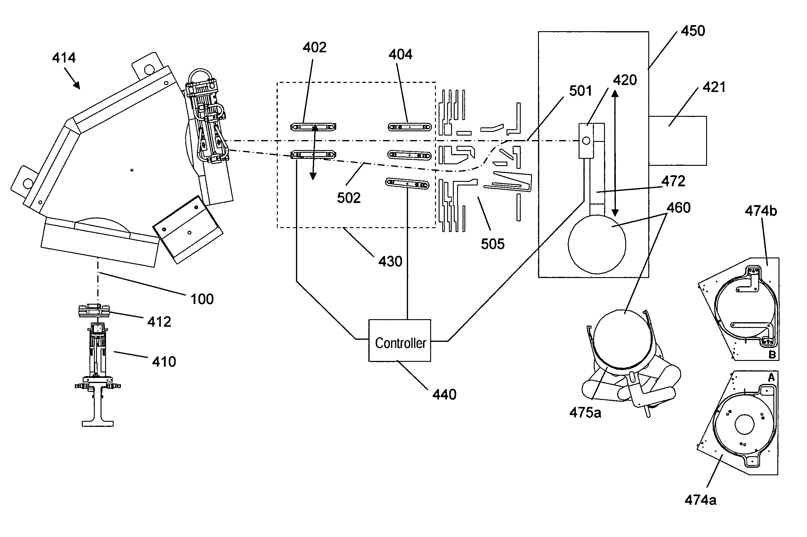
[0039]FIG. 3 is a perspective view of an ion implantation system of the present invention. The system comprises an ion source 102 that produces an ion beam 100 that emanates from a divergent extraction optics similar to those shown in FIG. 2, a mass analyzer magnet 414, and a collimator lens 200 As will be appreciated by those skilled in the art, these elements are housed in a vacuum enclosure (not shown). Magnet 414 comprises upper and lower coils 120, 121 and a yoke 110 with an entrance aperture 164 and an exit aperture 166. The magnet is curved over an arc of about 90°. The cross-section of the ion beam is relatively tall and thin and the longer dimension of the cross-section lies in the non-dispersive plane of magnet 110. The ion beam is slightly divergent upon exiting the extraction electrode; and as the beam travels along the beam path, it continues to become taller as the beam rays continue to diverge such that when it approaches the target (which may be a semiconductor wafer...
second embodiment
[0040] The analyzer magnet in FIG. 3 has a central passageway for the beam that has a top and bottom that are parallel from entrance aperture 164 to exit aperture 166. Thus, a cross-section of the magnet taken along lines A-A of FIG. 3 at any point along the radius of curvature of the magnet is the same. However the ion beam is diverging. In a second embodiment, the construction of the magnet is modified as illustrated by the three cross sections in FIGS. 4a, b, and c so that the height of the beam passage through the magnet increases as the beam expands. In particular, as shown in FIG. 4a, which depicts a cross-section closest to the entrance aperture 164 of the magnet, the height of the central passageway 160 is smallest. As shown in FIG. 4c, which depicts a cross-section closest to the exit aperture 166, the height of the central passageway is largest; and as shown in FIG. 4b which depicts a cross-section between those of FIGS. 4a and 4c, the height is intermediate that of the ot...
PUM
 Abstract
Description
Claims
Application Information
 - R&D
- Intellectual Property
- Life Sciences
- Materials
- Tech Scout
- Unparalleled Data Quality
- Higher Quality Content
- 60% Fewer Hallucinations
Browse by: Latest US Patents, China's latest patents, Technical Efficacy Thesaurus, Application Domain, Technology Topic, Popular Technical Reports.
© 2025 PatSnap. All rights reserved.Legal|Privacy policy|Modern Slavery Act Transparency Statement|Sitemap|About US| Contact US: help@patsnap.com


