
Devices for motile sperm separation

a technology of sperm separation and devices, applied in the field of male fertility tests, can solve the problems of not distinguishing between motile and non-motile spermatozoa, and achieve the effect of simple and cheap production

Inactive Publication Date: 2006-05-25
BRICKWOOD DAVID
View PDF0 Cites 14 Cited by
  • Summary
  • Abstract
  • Description
  • Claims
  • Application Information

AI Technical Summary

Benefits of technology

[0018] In order for motile spermatozoa in the sample to enter the separation medium, the inlet port and the separation medium must be in liquid communication. Preferably, however, such communication is initially prevented, thus preventing contamination of the medium via the inlet port before the device is used. This may also prevent the medium from escaping from the vessel via the inlet port, although this may be achieved anyway due to, for instance, viscosity or surface tension of the medium.
[0077] The device of the invention can be produced simply and cheaply. Furthermore, it can be used very easily, for instance by the home user. The invention thus provides an assay device which can be used at home as a basic screen of, for instance, male fertility.

Problems solved by technology

A disadvantage of these test kits is that they do not distinguish between motile and non-motile spermatozoa.
Moreover, they involve procedures which do not lend themselves to home use (e.g. centrifugation, microscopy), thus requiring implementation by a skilled practitioner.

Method used


Image

  • Devices for motile sperm separation
  • Devices for motile sperm separation
  • Devices for motile sperm separation

Examples


Embodiment Construction

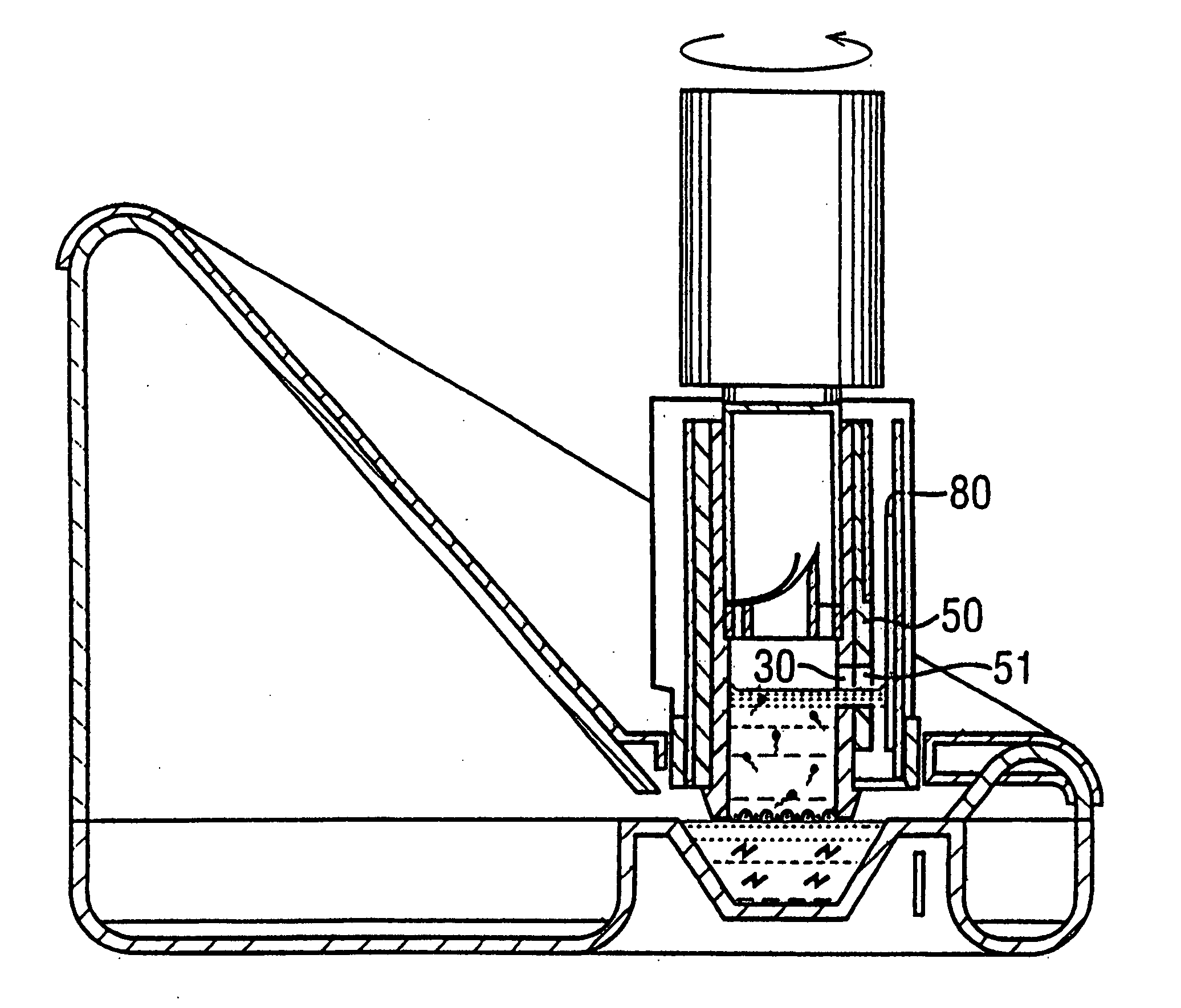
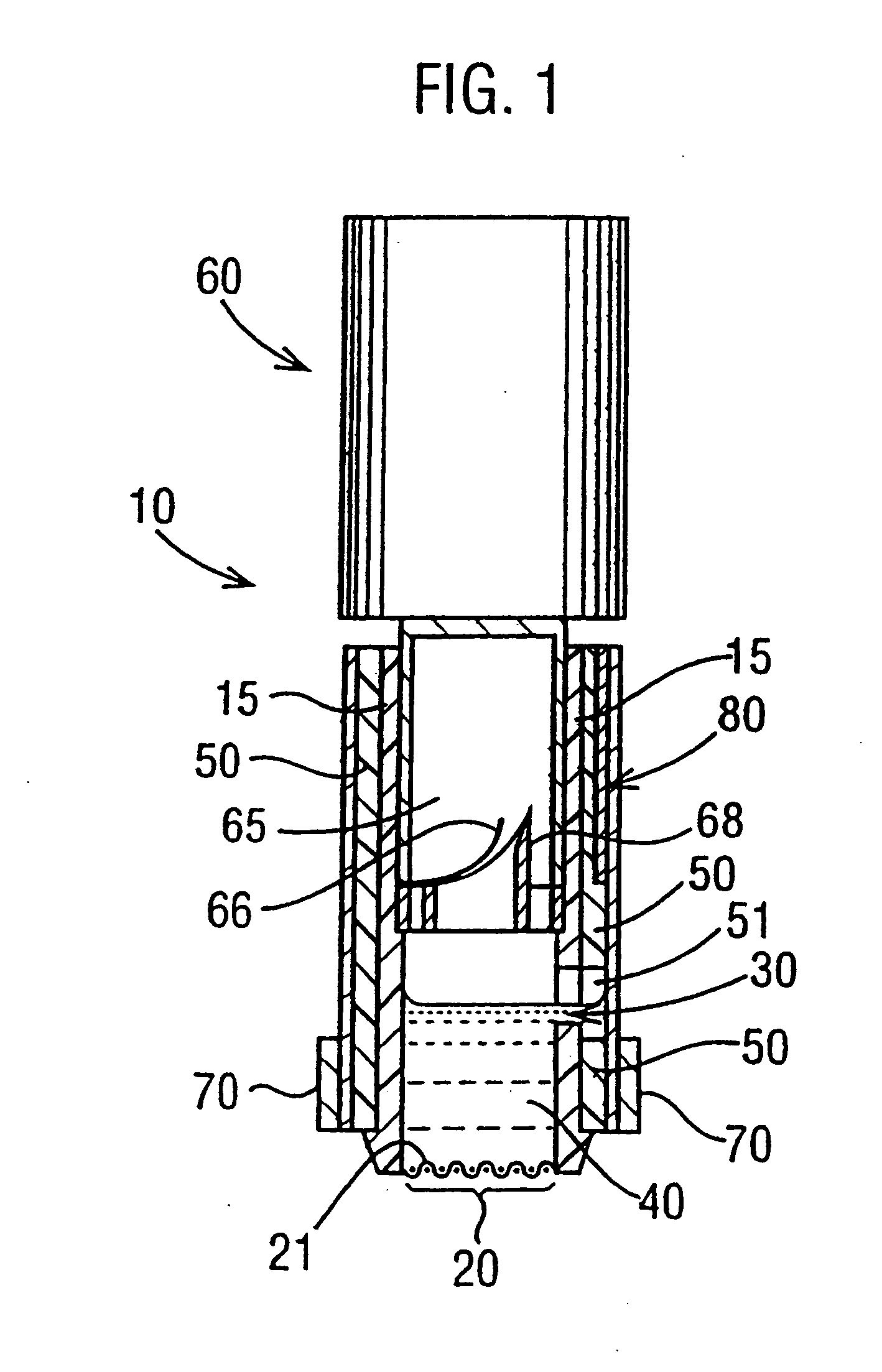
[0098] The device (10) shown in FIG. 1 comprises: a cylindrical plastic vessel (15); a sample inlet port (20), covered by a nylon mesh (21) formed from 0.15 mm strands spaced by 0.25 mm: a hole (30) in its side, shown in the open position: a solution (40) of EBSS supplemented with 0.88 mg / ml hyaluronic acid and 0.45% BSA; a plastic rotatable collar (50), including a hole (51) which is shown aligned with hole (30) to form an outlet port (35); a button (60, shown depressed), which houses a battery and circuitry for powering a circumferential heat source (70) and attached to which is a solution reservoir (65, shown empty), a foil seal (66, shown broken), and a hollow foil cutter (68); and an externally mounted test strip (80).

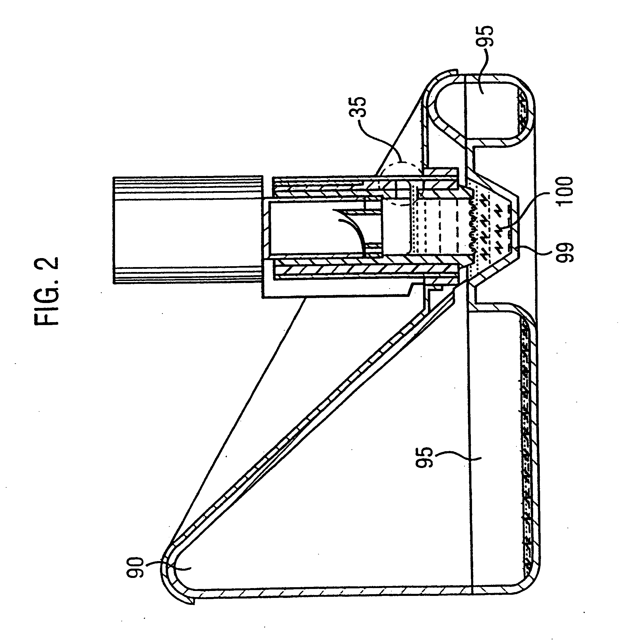
[0099]FIG. 2 shows the FIG. 1 device (10) attached to a semen receptacle (90) with sloped walls. A semen sample (100) has collected in the well (99) at the base of the receptacle (90), but some of it has overflowed into the receptacle overflow (95).

[0100]FIG. 3 ...


PUM

PropertyMeasurementUnit
lengthaaaaaaaaaa
diameteraaaaaaaaaa
pore sizeaaaaaaaaaa

Abstract

Device (10, 110) for separating motile sperm from a sample (100, 200), comprises a vessel (15, 115) having an inlet port (20, 120), an outlet port (35, 135) which is initially closed, a medium (40, 140) into which motile sperm in the sample (100, 200) can migrate into the vessel (15, 115) via the inlet (20, 120), and an actuator (50, 150), the operation of which opens the outlet (35, 135), thereby allowing the medium (40, 140) to flow out of the vessel (15, 115) through the outlet (35, 135). The medium (40, 140) in the vessel (15, 115) is initially prevented from flowing through the outlet (35, 135), thus allowing an incubation period which allows motile sperm sufficient time to migrate from the sample (100, 200) into the medium (40, 140) before the medium (40, 140) leaves the vessel (35, 135). The device (10, 110) preferably comprises a spermatozoa detector in communication with the outlet. In devices for separating sperm, capillary flow takes place through non-fibrous material, such as the space between sheets (81a and 81b; 181a and 181b) of closely-juxtaposed material. A device for separating motile and non-motile sperm includes a temperature sensor, a heat source (70, 170) and, optionally, a temperature regulator.

Description

[0001] All documents cited herein are incorporated by reference in their entirety. TECHNICAL FIELD [0002] This invention is in the field of male fertility tests, more specifically tests for separating and detecting motile spermatozoa in a semen sample. BACKGROUND ART [0003] Approximately 15% of couples attempting to conceive fail to do so within one year of unprotected intercourse. Fertility specialists define these couples is being infertile. 40% of these cases result from male factors. In a substantial proportion of these treatment, is available to ameliorate or relieve the condition which leads to infertility. [0004] Other conditions also exist in which it is desirable to test for the presence or otherwise of viable spermatozoa in a sample. For example, vasectomies are now frequently carried out as a method of contraception, but it is necessary to confirm that ejaculate is free of viable spermatozoa after the operation. [0005] A number of methods exist for assessing the motility ...

Claims


Application Information

Patent Timeline
Patent Type & Authority Applications(United States)
IPC IPC(8): C12M1/34G01N33/50G01N33/53
CPCC12N5/0612G01N33/689G01N2333/70596G01N2800/367
Inventor BRICKWOOD, DAVID
Owner BRICKWOOD DAVID
Learn More