Ball roller bearing, in particular for absorbing combined radial and axial loads

a ball roller bearing and combined radial and axial load technology, which is applied in the direction of roller bearings, bearings, bearing components, etc., can solve the problems of unsuitable applications with high tilting resistance and combined radial and axial forces, the ability of ball roller bearings to be loaded with axial forces is subject to quite narrow limits, and the type of ball roller bearings has proved to be disadvantageous, etc., to achieve simple and cheap production, increase the tilting play of the ball roller

Inactive Publication Date: 2014-04-08
SCHAEFFLER TECH AG & CO KG
View PDF12 Cites 0 Cited by
  • Summary
  • Abstract
  • Description
  • Claims
  • Application Information

AI Technical Summary

Benefits of technology

[0008]Taking the presented disadvantages of the solutions of the known prior art as a starting point, the invention is therefore based on the object of designing a ball roller bearing, in particular for accommodating combined radial and axial loads, which can be produced simply and cheaply and which can be assembled with little expenditure to form a transportable structural unit and in which premature wear as a result of increased tilting play of the ball rollers and as a result of bracing effects in the bearing cage are eliminated.
[0015]Furthermore, in an expedient refinement of the ball roller bearing, when the bearing is at a standstill, the ball rollers can be fixed in a starting position in which, when the ball roller bearing starts to rotate, they are immediately aligned in their precise angular positions corresponding to their contact angle axes, and in the circumferential direction. Here, the ball rollers bear in each case alternately with an edge region of their running surfaces against the obliquely formed pocket bases of the cage pockets of one comb-type cage, and are simultaneously aligned with one of their side surfaces against the undersides of the lugs of the other comb-type cage. Tumbling of the ball rollers on their raceway segments transversely with respect to the circumferential direction thereof, and therefore bracing effects between the ball rollers and their comb-type cages, are thereby avoided when the ball roller bearing starts to rotate.

Problems solved by technology

Although a ball roller bearing of said type is characterized by a high filling ratio with rolling bodies, and therefore a significantly increased radial load-bearing capacity, in relation to a deep-groove ball bearing of the same design, said ball roller bearing simultaneously has the disadvantage that the capability thereof to be loaded with axial forces is subjected to quite narrow limits and it is therefore unsuitable for applications with high tilting resistance and high combined radial and axial forces.
A ball roller bearing of said type has however proven to be disadvantageous from numerous aspects, in particular on account of the two-part design of one of the two bearing rings.
The two-part design of one of the bearing rings requires increased production and assembly expenditure not only as a result of the increased number of components but also as a result of the need for highly precise production of the tolerance-afflicted parting point between the two ring parts, which increased production and assembly expenditure has an adverse effect on the production costs of a ball roller bearing of said type.
Furthermore, the two-part design of one of the bearing rings has the effect that, despite cumbersome bracing of the two bearing rings during bearing operation as a result of arising settling effects, loosening of the assembly can occur, as a result of which the tilting play of the ball rollers is disadvantageously increased, resulting in premature wear of the ball roller bearing.
It is likewise disadvantageous that a transportable structural unit cannot be formed with split bearing rings.
Finally, the single-piece design of the bearing cage as a window-type cage in such ball roller bearings has proven to be disadvantageous because, in certain load states of the bearing, different relative rotational speeds can arise between the ball rollers inclined with their contact angle axes inclined in one direction and the ball rollers inclined with their contact angle axes in the other direction, as a result of which bracing effects can arise in the bearing cage and increased friction can occur between the ball rollers and their cage pockets in the bearing cage, and which likewise contribute to premature wear of the ball roller bearing.

Method used


Image

  • Ball roller bearing, in particular for absorbing combined radial and axial loads
  • Ball roller bearing, in particular for absorbing combined radial and axial loads
  • Ball roller bearing, in particular for absorbing combined radial and axial loads

Examples


Embodiment Construction

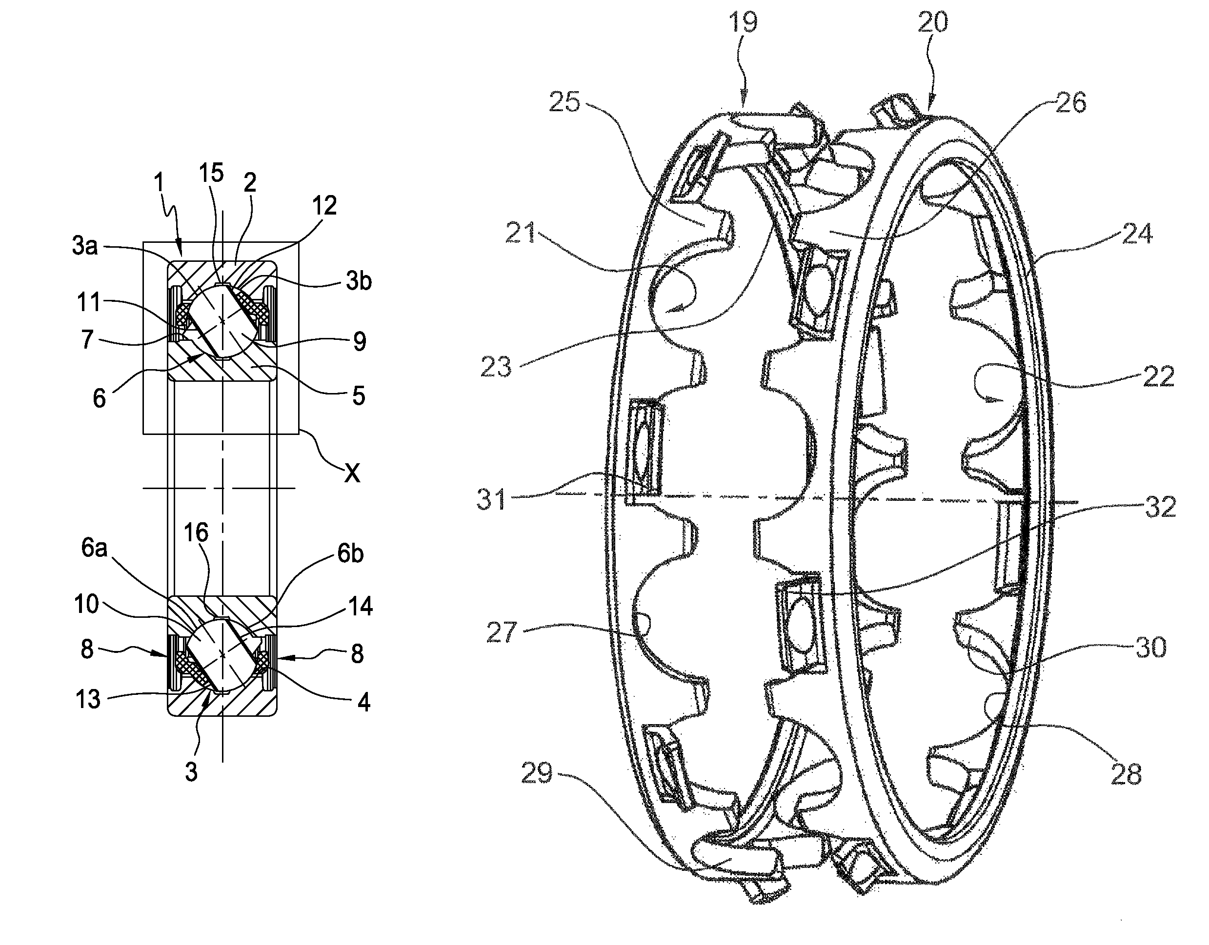
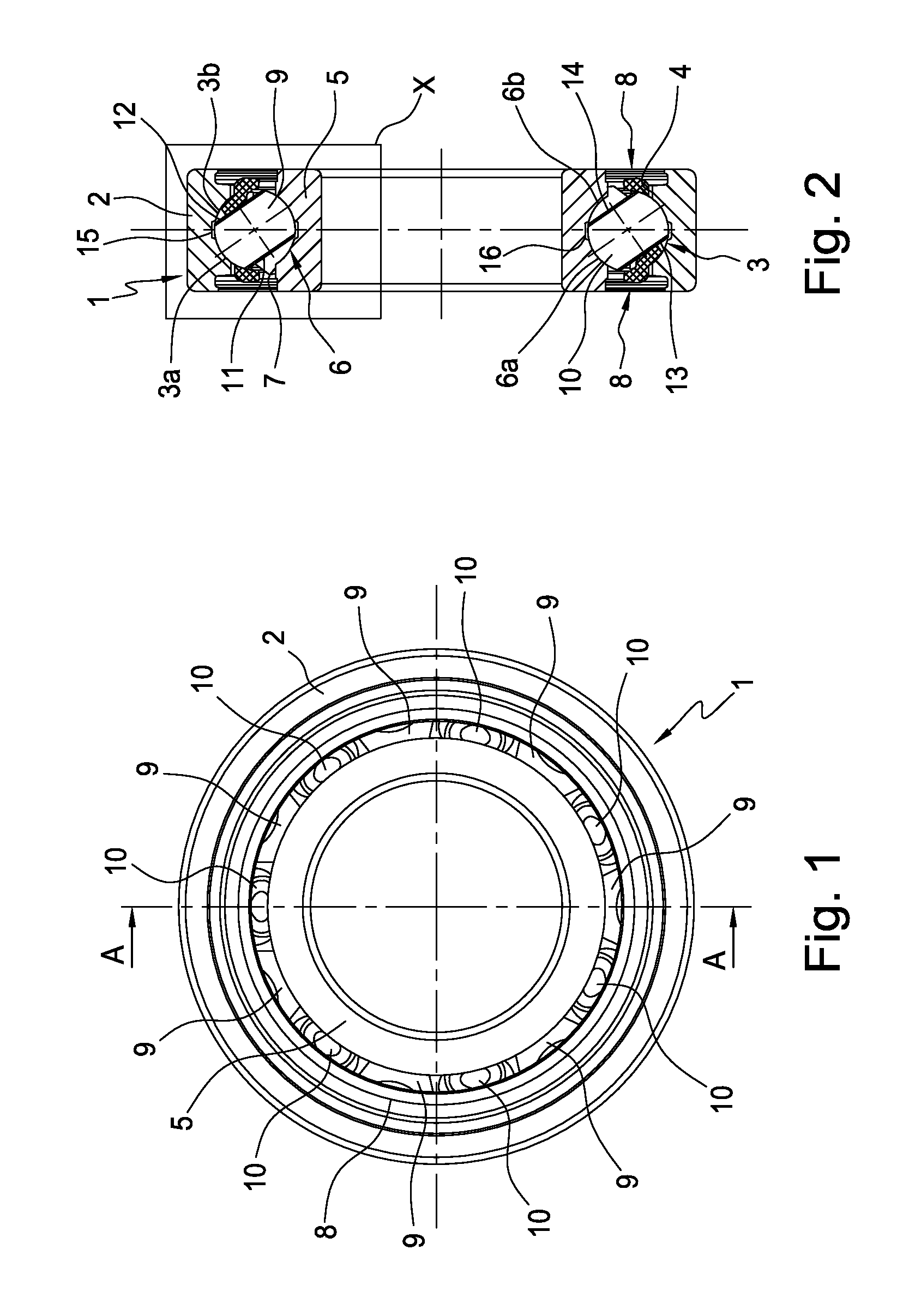
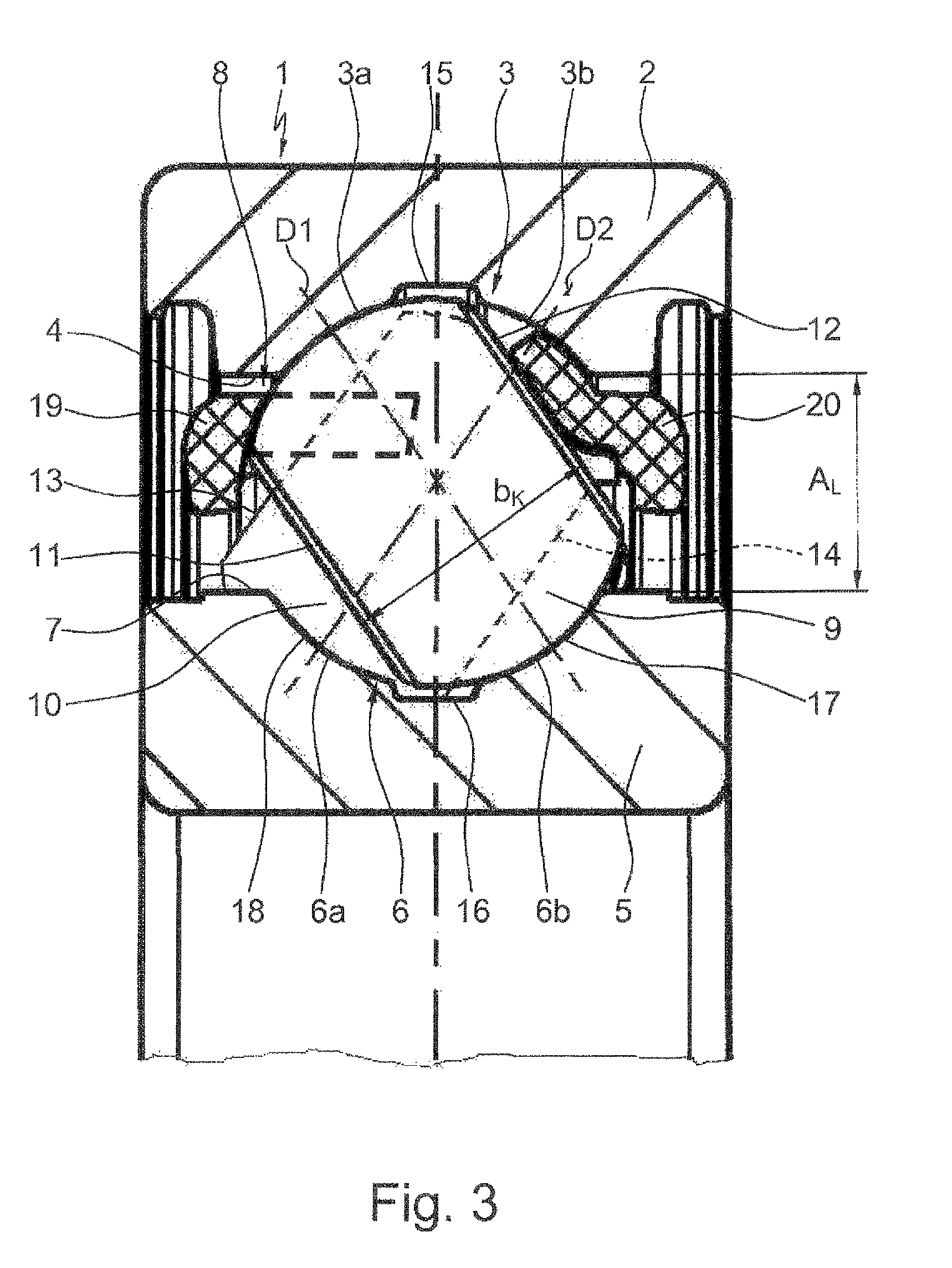
[0023]FIGS. 1 and 2 clearly show a ball roller bearing 1 which is suitable for combined radial and axial loads and which is composed substantially of an outer bearing ring 2 with a channel-shaped raceway 3 on the inner side 4 thereof, and of an inner bearing ring 5 with a channel-shaped raceway 6 on the outer side 7 thereof, and of a multiplicity of ball rollers 9, 10, which ball rollers roll between said bearing rings 2, 5 in the raceways 3, 6 and which ball rollers are held with uniform spacings to one another in the circumferential direction by a bearing cage 8. Here, it can be seen in FIGS. 2 and 3 that the ball rollers 9, 10 have in each case two side surfaces 11, 12 and 13, 14, which side surfaces are flattened symmetrically proceeding from a spherical basic shape and are arranged parallel to one another, and which ball rollers are also formed with a width BK between said side surfaces 11, 12 and 13, 14, which width is dimensioned to be larger than the radial spacing AL, betwe...


PUM


Abstract

A ball roller bearing, which has an outer and inner bearing ring with a groove-shaped raceways and ball rollers, which roll between the bearing rings in the raceways. The rollers are held at distances from each other in the circumferential direction by a bearing cage and which have a width that is dimensioned larger than the radial distance between the inside and the outside of the bearing rings. The raceways are divided into two segments by an axially centered annular groove such that a first ball roller rolls on two first diagonally opposed track segments and a second ball roller rolls on two second diagonally opposed track segments of the bearing rings. Both bearing rings are single-piece components, and the bearing cage is formed by two identical double prong-type cages acting independently of each other. The bearing is filled with the ball rollers by an axial tilt cam assembly method.

Description

CROSS-REFERENCE TO RELATED APPLICATIONS[0001]This application is a 371 of PCT / EP2010 / 053631 filed Mar. 19, 2010, which in turn claims the priority of DE 10 2009 0114 169.3 filed Mar. 20, 2009. The priority of both applications is hereby claimed and both applications are incorporated by reference herein.FIELD OF THE INVENTION[0002]The invention relates to a ball roller bearing that can be used for applications with high tilting resistance and combined radial and axial forces. For example, the roller bearing can be used for mounting of belt tensioning pulleys for the traction mechanism drive of internal combustion engines.BACKGROUND OF THE INVENTION[0003]Ball roller bearings are rolling bearings with special rolling bodies designed as ball rollers, which ball rollers, proceeding from a spherical basic shape, have in each case two side surfaces which are flattened from said spherical basic shape and which are arranged parallel to one another and between which in each case the running s...

Claims


Application Information

Patent Timeline
Patent Type & Authority Patents(United States)
IPC IPC(8): F16C33/34F16C33/41F16C33/38F16C33/60
CPCF16C19/36F16C43/06F16C33/491F16C33/36
Inventor DOEPPLING, HORSTHOFMANN, HEINRICHGEIGER, ERNSTMASUR, ERNST
Owner SCHAEFFLER TECH AG & CO KG
Why Eureka
Try Eureka