Hydraulic mount and method of producing a hydraulic mount

a technology of hydraulic mount and mounting plate, which is applied in the direction of shock absorbers, other domestic objects, transportation and packaging, etc., can solve the problems of high production cost, negative damping performance, and complex construction of the mount, and achieve the effect of small space requirement and simple and cheap production

Active Publication Date: 2021-03-04
SUMITOMO RIKO CO LTD
View PDF5 Cites 2 Cited by
  • Summary
  • Abstract
  • Description
  • Claims
  • Application Information

AI Technical Summary

Benefits of technology

[0005]The present disclosure provides a hydraulic mount with a relatively small space requirement, which can be produced simply and cheaply.

Problems solved by technology

From the point of view of their construction, however, they are very complex and therefore expensive to produce.
In the European patent specification 0 458 008 B1, for example, a suspension strut support mount is described in which the support spring lies outside the hydraulic module, which has a negative effect on the damping performance since the hydraulic module only operates in a certain amplitude range.
Moreover, the construction of this mount is very complex and consists of many individual parts.

Method used


Image

  • Hydraulic mount and method of producing a hydraulic mount
  • Hydraulic mount and method of producing a hydraulic mount
  • Hydraulic mount and method of producing a hydraulic mount

Examples


Embodiment Construction

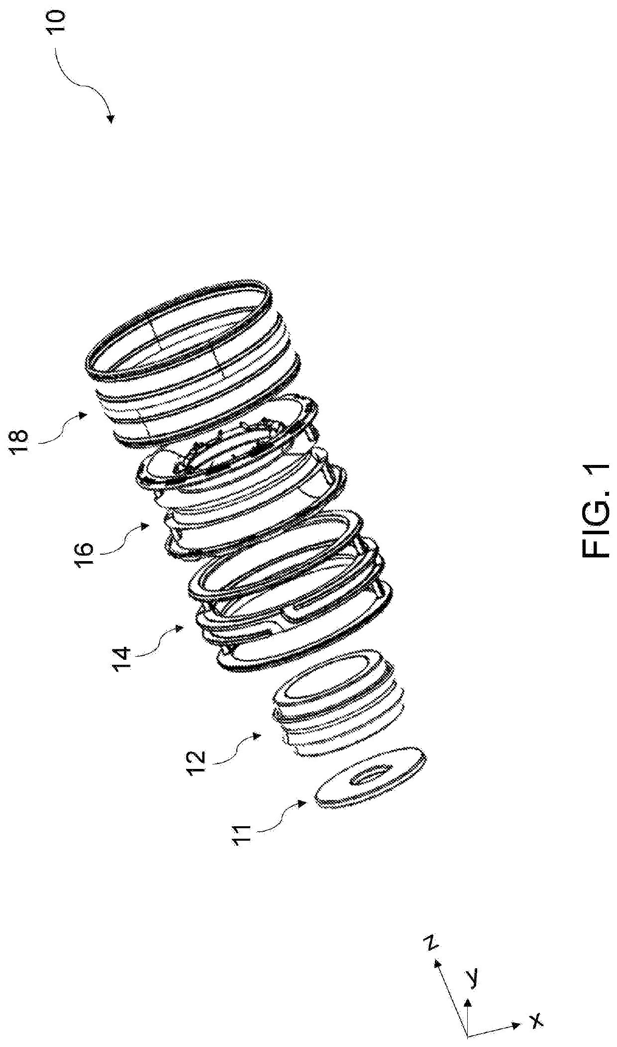
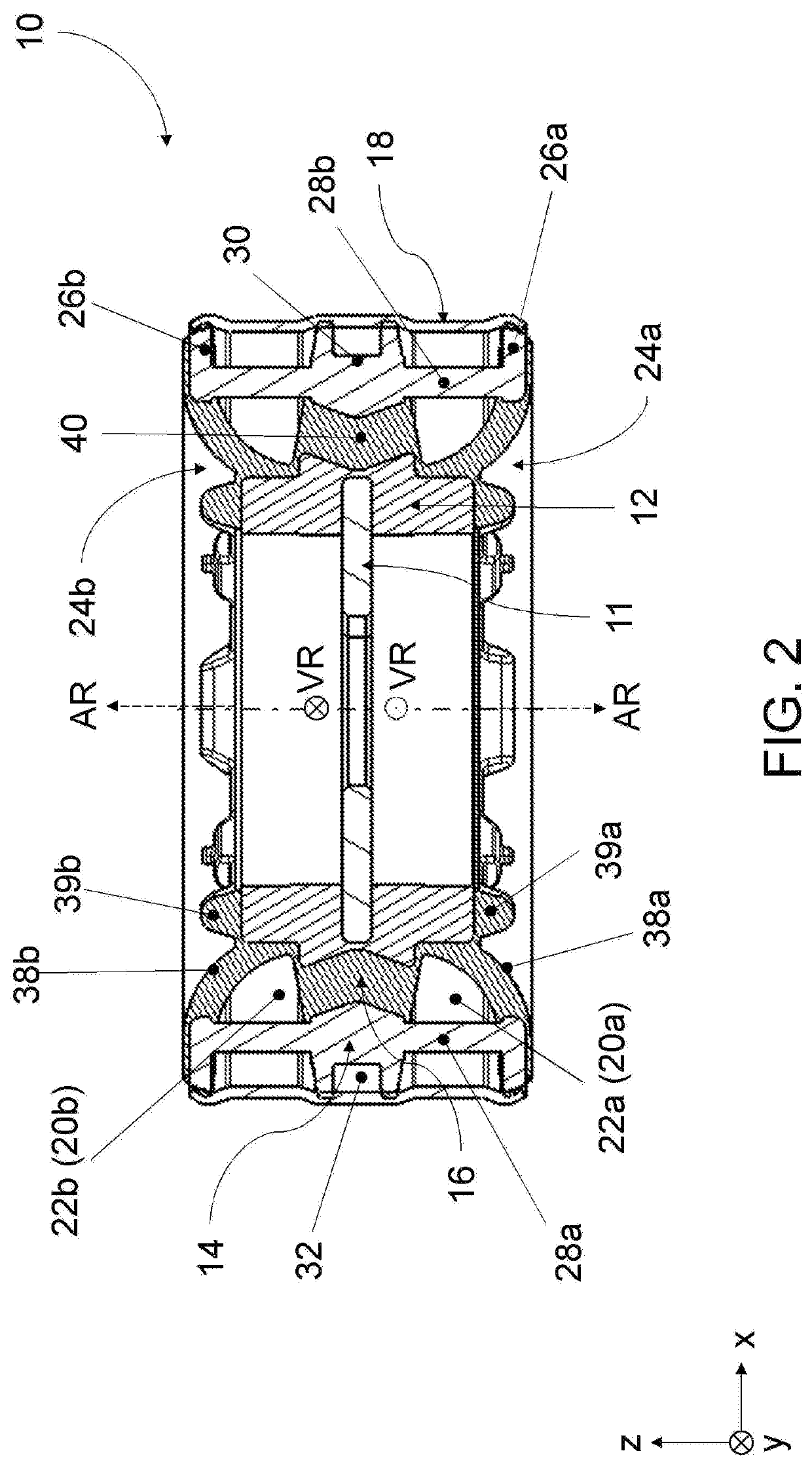
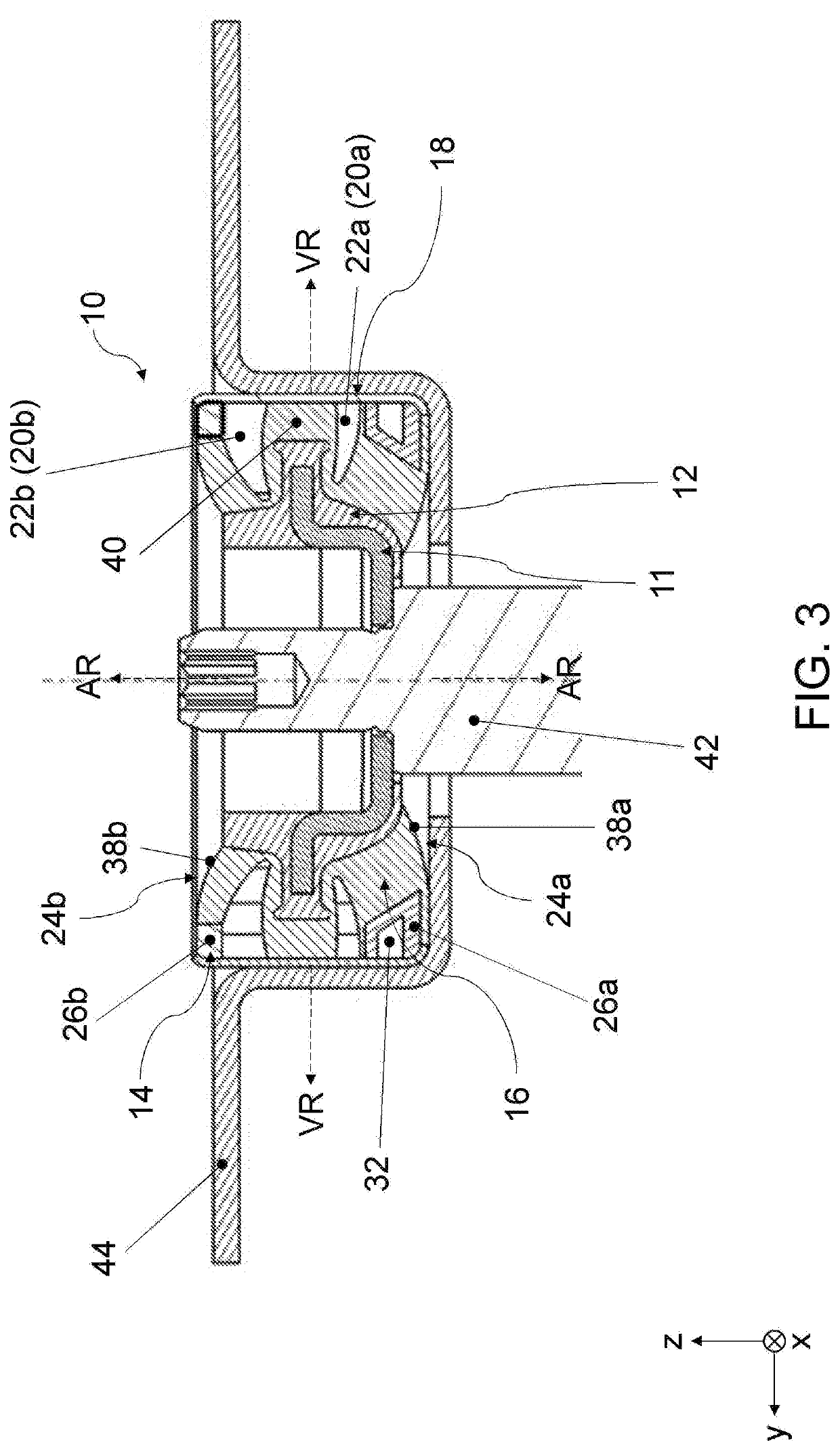
[0053]FIG. 1 shows the construction of the mount 10 with the aid of an exploded view. The mount 10 comprises an annular mounting disc 11, which is overmolded with a plastic to form the inner core 12. The inner core 12 together with the mounting disc 11 is inserted in a mold with the cage 14. Elastomer material is then injected into the mold and around the cage 14 and around the inner core 12, whereby the elastomer body 16 is shaped and vulcanized on to the cage 14 and the inner core 12. The elastomer body 16 is shaped in such a way that, both in an axial direction and in at least two mutually opposite radial directions, it has no undercuts. After demolding, the outer sleeve 18 is connected to the cage 14 or the elastomer body. The unit comprising—from inside to outside—the mounting disc 11, the inner core 12, the elastomer body 16 and the cage 14 is pushed or pressed into the outer sleeve 18, or the outer sleeve 18 is placed or pushed over this unit and optionally calibrated or pres...


PUM

PropertyMeasurementUnit
damping performanceaaaaaaaaaa
dampingaaaaaaaaaa
frequencyaaaaaaaaaa

Abstract

A hydraulic mount is provided and includes: an inner core, a cage that surrounds the inner core, an elastomer body that extends between the inner core and the cage and elastically connects them to each other, and an outer sleeve that encloses the cage. The elastomer body has a first circumferential fluid chamber recess and a second circumferential fluid chamber recess. The first fluid chamber recess and the second fluid chamber recess are each limited in a radially outwards direction by the outer sleeve to form a first fluid chamber and a second fluid chamber. The elastomer body is configured to be substantially undercut-free in an axial direction on its axial end faces. The elastomer body and the cage are configured to be substantially undercut-free in the region of the first fluid chamber recess and the second fluid chamber recess, at least in two predetermined, mutually opposite radial directions.

Description

CROSS REFERENCE TO RELATED APPLICATIONS[0001]This application claims the priority benefit of German Patent Application No. 10 2019 006 047.4, filed on Aug. 27, 2019. The entirety of the above-mentioned patent application is hereby incorporated by reference herein and made a part of this specification.TECHNICAL FIELD[0002]The disclosure relates to a hydraulic mount, such as a suspension strut support mount, and to a method of producing a hydraulic mount, such as a suspension strut support mount.BACKGROUND ART[0003]Hydraulic suspension strut support mounts already exist in the prior art. From the point of view of their construction, however, they are very complex and therefore expensive to produce.[0004]In the European patent specification 0 458 008 B1, for example, a suspension strut support mount is described in which the support spring lies outside the hydraulic module, which has a negative effect on the damping performance since the hydraulic module only operates in a certain ampl...

Claims


Application Information

Patent Timeline
Patent Type & Authority Applications(United States)
IPC IPC(8): F16F13/14B29C45/14
CPCF16F13/14F16F13/1481F16F13/1463F16F13/1445B60G15/067B29C45/14008B29C45/14491B60G2204/128F16F2226/04B29C45/14819F16C33/30B29C45/14F16C2220/00B60G13/003B60G2204/41062B60G2206/81012B60G2500/10B29K2021/006B29L2031/30B29K2021/003
Inventor KONDOR, JOZSEFLEIP, DENNIS
Owner SUMITOMO RIKO CO LTD
Why Eureka
Try Eureka