Mop-Head Plate Comprising Mop Cover

a mop cover and mop technology, applied in the field of mop, can solve the problems of increased danger of breakage, difficult opening of the clamp connection, and increased danger of injury

Active Publication Date: 2008-01-17
CARL FREUDENBERG KG
View PDF3 Cites 2 Cited by
  • Summary
  • Abstract
  • Description
  • Claims
  • Application Information

AI Technical Summary

Problems solved by technology

A clamp connection is difficult to open and harbors the danger of injury if the clamping force is grea

Method used


Image

  • Mop-Head Plate Comprising Mop Cover
  • Mop-Head Plate Comprising Mop Cover
  • Mop-Head Plate Comprising Mop Cover

Examples


Embodiment Construction

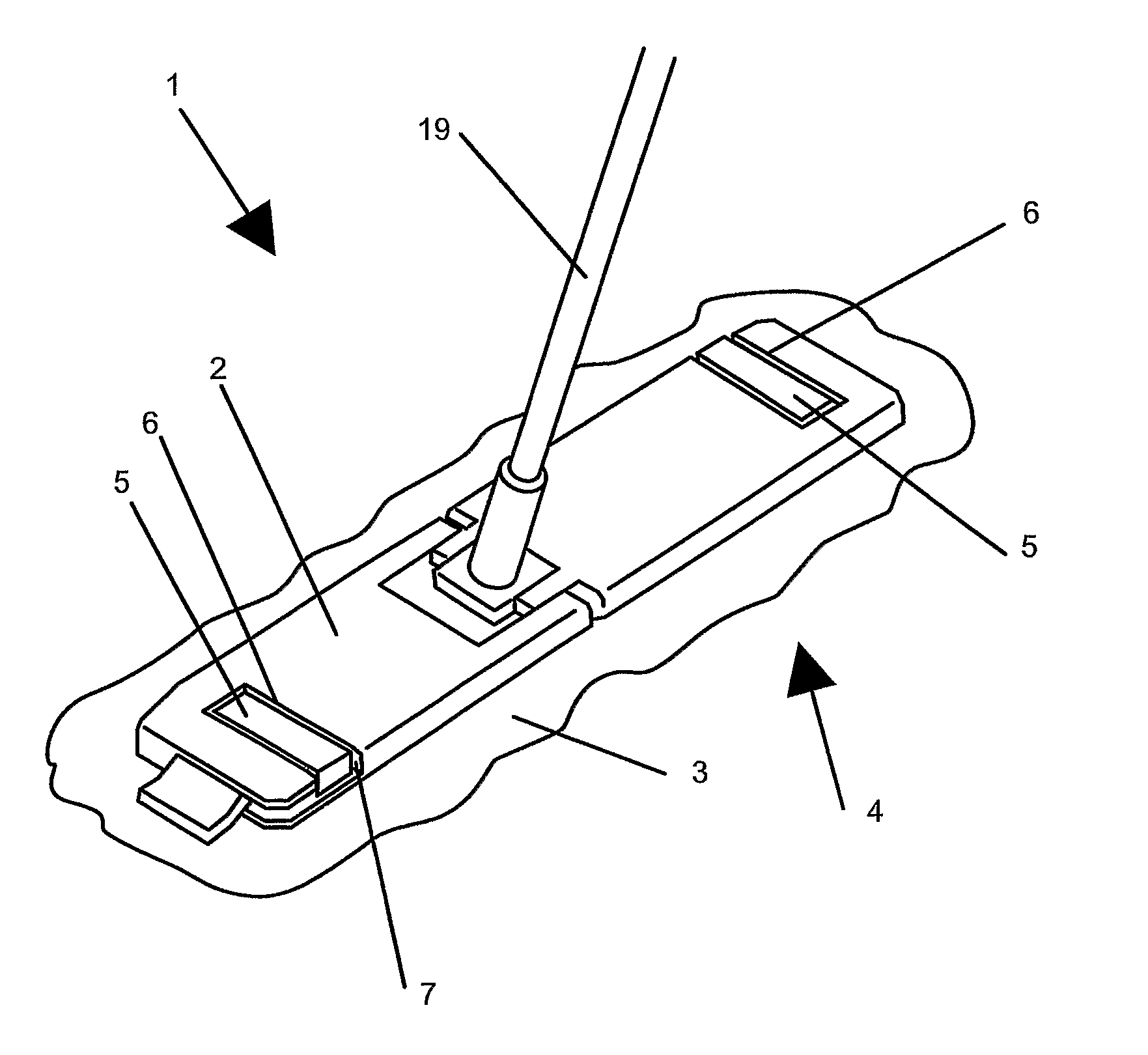
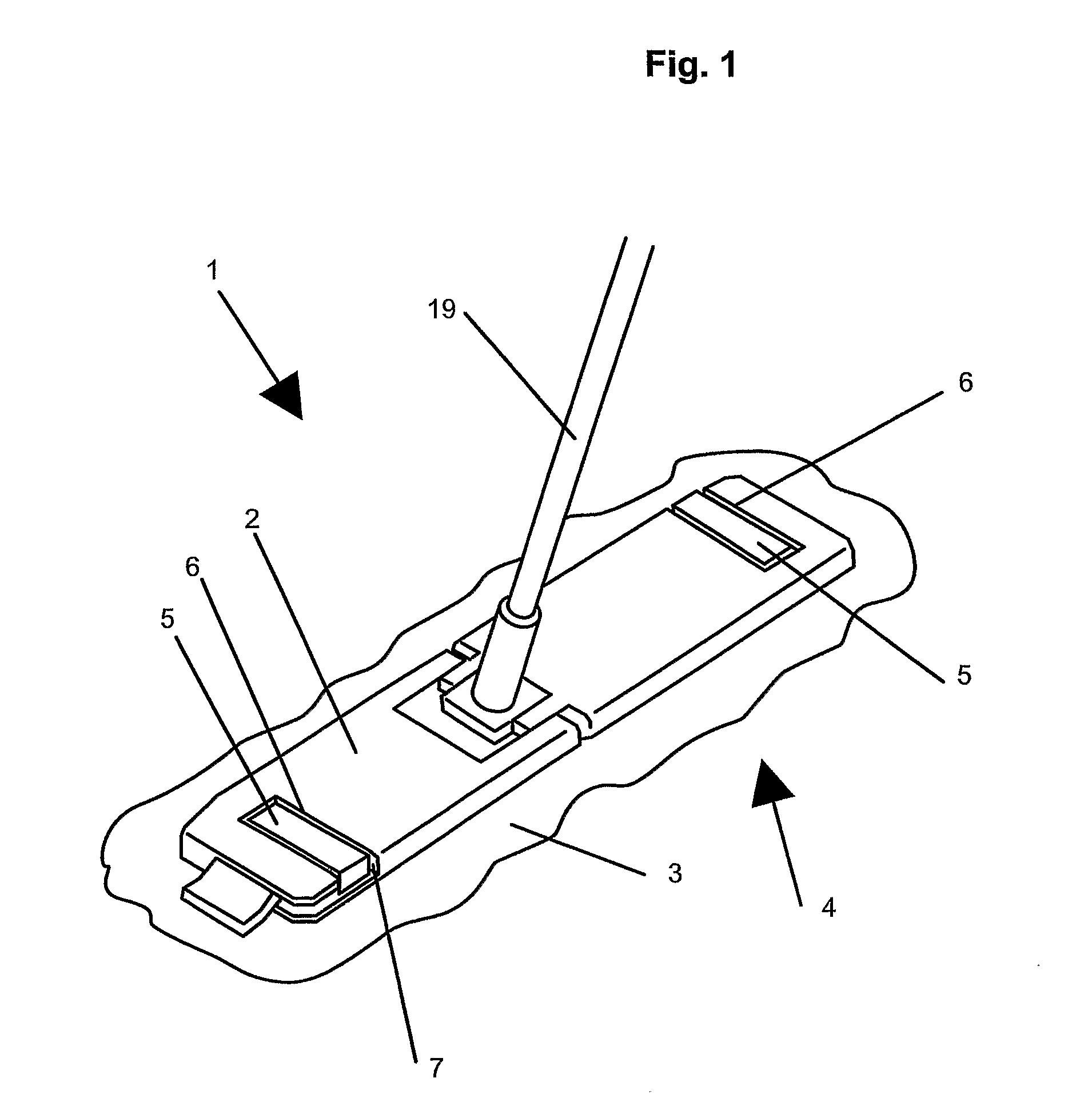
[0004] The invention is based on the task of making a farther development in the known mop so that the mop cover can be exchanged with little effort and is reliably held on the mop plate during mopping,

[0005] This task is solved by the characteristics of Claims 1 and 7. The dependent claims refer to advantageous embodiments.

[0006] To solve the task, at least one receptacle in the mop plate is formed by a recess and the corresponding holding device is disposed in the recess in a positive locking fashion (form-fitted) and can be nondestructively removed. Through the positive locking connection of the holding device of the mop cover and the recess of the mop plate, the mop cover is more reliably affixed to the mop plate during mopping and wringing. Because of the form-fit, only low attachment force is necessary for a reliable connection. Through the low forces of attachment and the absence of moving parts for attachment changing the mop cover becomes simpler and the danger of injury ...


PUM

PropertyMeasurementUnit
Elasticityaaaaaaaaaa

Abstract

The invention relates to a mop (1) comprising a mop-head plate (2) and an interchangeable mop cover (3) with a mopping surface (4) that is attached to the mop-head plate (2). According to the invention, the mop cover (3) is equipped on two opposing sides with a respective fixing device (5), which engages in a respective retainer (6) of the mop-head plate (2). At least one retainer (6) is formed by a recess (7) and the corresponding fixing device (5) is held by a positive fit in the recess (7) so that it can be detached without sustaining any damage.

Description

TECHNICAL FIELD [0001] The invention concerns a mop consisting of a mop plate and a mop cover having a mop surface that is exchangeably affixed to the mop plate, where the mop cover has a securing device at each of its two opposite sides, each of which engages with a recess in the mop plate. PRIOR ART [0002] A mop with a mop plate on which a mop cover can be separably affixed is known from DE 37 45 013 C2. The attachment is done by clamping the ends of the material that are formed as a continuation of the material. Clamping takes place by means of hinged straps that are arranged on the side of the mop plate away from the mop surface. The clamping effect is determined by the thickness of the material of the material ends. The holding power of the connection is determined by the material thickness of the material end and for this reason can vary. [0003] A clamp connection is difficult to open and harbors the danger of injury if the clamping force is great. Movable parts are necessary ...

Claims


Application Information

Patent Timeline
IPC IPC(8): A47L13/20A47L13/254A47L13/256A47L13/258
CPCA47L13/20A47L13/258A47L13/256
Inventor LINDNER, FALKEISENHUT, ANDREASMASIH, MICHAELGRATZKI, TORSTEN
Owner CARL FREUDENBERG KG
Why Eureka
Try Eureka