Mop-head plate comprising mop cover

a mop plate and mop cover technology, applied in the field of mop, can solve the problems of reducing the danger of injury, and achieve the effect of reliably holding the mop plate during mopping and reducing the effor

Active Publication Date: 2011-05-12
CARL FREUDENBERG KG
View PDF4 Cites 2 Cited by
  • Summary
  • Abstract
  • Description
  • Claims
  • Application Information

AI Technical Summary

Benefits of technology

[0006]To solve the task, at least one receptacle in the mop plate is formed by a recess and the corresponding holding device is disposed in the recess in a positive locking fashion [form-fitted] and can be nondestructively removed. Through the positive locking connection of the holding device of the mop cover and the recess of the mop plate, the mop cover is more reliably affixed to the mop plate during mopping and wringing. Because of the form-fit, only low attachment force is necessary for a reliable connection. Through the low forces of attachment and the absence of moving parts for attachment changing the mop cover becomes simpler and the danger of injury decreases. The mop plate and mop cover have few parts and can be produced simply and cheaply.
[0019]The mop cover can have a mopping surface on the top side and bottom side. Use of two sides can increase the useful life of the mop, and, for another thing, different mop cover surfaces can be specified for specific surfaces to be cleaned.

Problems solved by technology

Through the low forces of attachment and the absence of moving parts for attachment changing the mop cover becomes simpler and the danger of injury decreases.

Method used


Image

  • Mop-head plate comprising mop cover
  • Mop-head plate comprising mop cover
  • Mop-head plate comprising mop cover

Examples


Embodiment Construction

[0027]FIG. 1 shows a mop 1 with a mop plate 2 and a mop cover 3 with mop surface 4 exchangeably affixed to the mop plate 2. The mop plate 2 is hinged to a handle 19. The mop cover 3 has at each of its two opposite ends a holding device 5, each of which engages with a receptacle 6 in mop plate 2. The receptacles 6 in mop plate 2 are formed by recesses 7, which are arranged on the side of the mop plate turned away from the mopping surface 4. The holding devices 5 are arranged in recesses 7 in a positive locking fashion [form-fit] and can be removed nondestructively. The mop plate 2 is foldable along an axis that extends across its lengthwise axis.

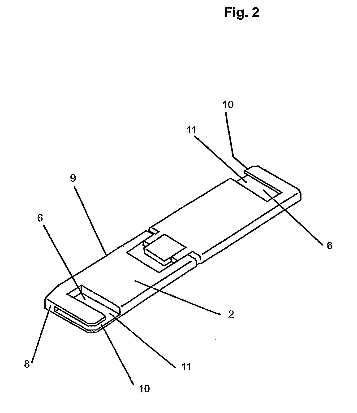
[0028]FIG. 2 shows a mop plate 2 with two receptacles 6, which are arranged on the sides turned away from the mopping surface 4. The receptacles 6 are formed by a slot 10 that is disposed on a transverse edge 8 and is open to a lengthwise edge 9 of the mop plate 2 and extends parallel to mop plate 2 and by a rectangular undercut 11 that is op...


PUM

PropertyMeasurementUnit
elasticaaaaaaaaaa
thicknessaaaaaaaaaa
clamping forceaaaaaaaaaa

Abstract

The invention relates to a mop (1) comprising a mop-head plate (2) and an interchangeable mop cover (3) with a mopping surface (4) that is attached to the mop-head plate (2). According to the invention, the mop cover (3) is equipped on two opposing sides with a respective fixing device (5), which engages in a respective retainer (6) of the mop-head plate (2). At least one retainer (6) is formed by a recess (7) and the corresponding fixing device (5) is held by a positive fit in the recess (7) so that it can be detached without sustaining any damage.

Description

TECHNICAL FIELD[0001]The invention concerns a mop consisting of a mop plate and a mop cover having a mop surface that is exchangeably affixed to the mop plate, where the mop cover has a securing device at each of its two opposite sides, each of which engages with a recess in the mop plate.BACKGROUND OF THE INVENTION[0002]A mop with a mop plate on which a mop cover can be separably affixed is known from DE 37 45 013 C2. The attachment is done by clamping the ends of the material that are formed as a continuation of the material. Clamping takes place by means of hinged straps that are arranged on the side of the mop plate away from the mop surface. The clamping effect is determined by the thickness of the material of the material ends. The holding power of the connection is determined by the material thickness of the material end and for this reason can vary.[0003]A clamp connection is difficult to open and harbors the danger of injury if the clamping force is great. Movable parts are...

Claims


Application Information

Patent Timeline
Patent Type & Authority Applications(United States)
IPC IPC(8): A47L13/20A47L13/254A47L13/256A47L13/258
CPCA47L13/20A47L13/258A47L13/256
Inventor LINDNER, FALKEISENHUT, ANDREASMASIH, MICHAELGRATZKI, TORSTEN
Owner CARL FREUDENBERG KG
Why Eureka
Try Eureka