Surface emitting device, backside illumination device, and liquid crystal display device

a liquid crystal display and surface technology, applied in lighting device details, lighting and heating equipment, instruments, etc., can solve problems such as interference fringes and moire patterns, and achieve the effect of preventing moire patterns

Inactive Publication Date: 2006-05-25
ALPS ALPINE CO LTD
View PDF10 Cites 24 Cited by
  • Summary
  • Abstract
  • Description
  • Claims
  • Application Information

AI Technical Summary

Benefits of technology

The invention is a surface emitting device that can emit light from its entire surface without unevenness or umbrae, and prevent the occurrence of a moire pattern when combined with a liquid crystal display panel. The device includes a light source and a light-guiding plate with minute prisms formed at its surface. The prisms have easy and steep slopes and intersect each other at a predetermined angle. The device also includes a reflecting plate and a prism sheet for a backside illumination device, and a liquid crystal display panel for a liquid crystal display device. The front-side illumination device includes the light-guiding plate and a reflective liquid crystal display unit. The technical effects of the invention are improved light emission and reduced unevenness and moire pattern.

Problems solved by technology

However, when the surface emitting device disclosed in Japanese Unexamined Patent Application Publication No. 2003-257229 is used to illuminate the liquid crystal display panel, there is a problem in that a moire pattern(interference fringes) occurs due to the interference between liquid crystal pixels and the minute grooves (prisms) formed at the light emission surface.

Method used


Image

  • Surface emitting device, backside illumination device, and liquid crystal display device
  • Surface emitting device, backside illumination device, and liquid crystal display device
  • Surface emitting device, backside illumination device, and liquid crystal display device

Examples


first example

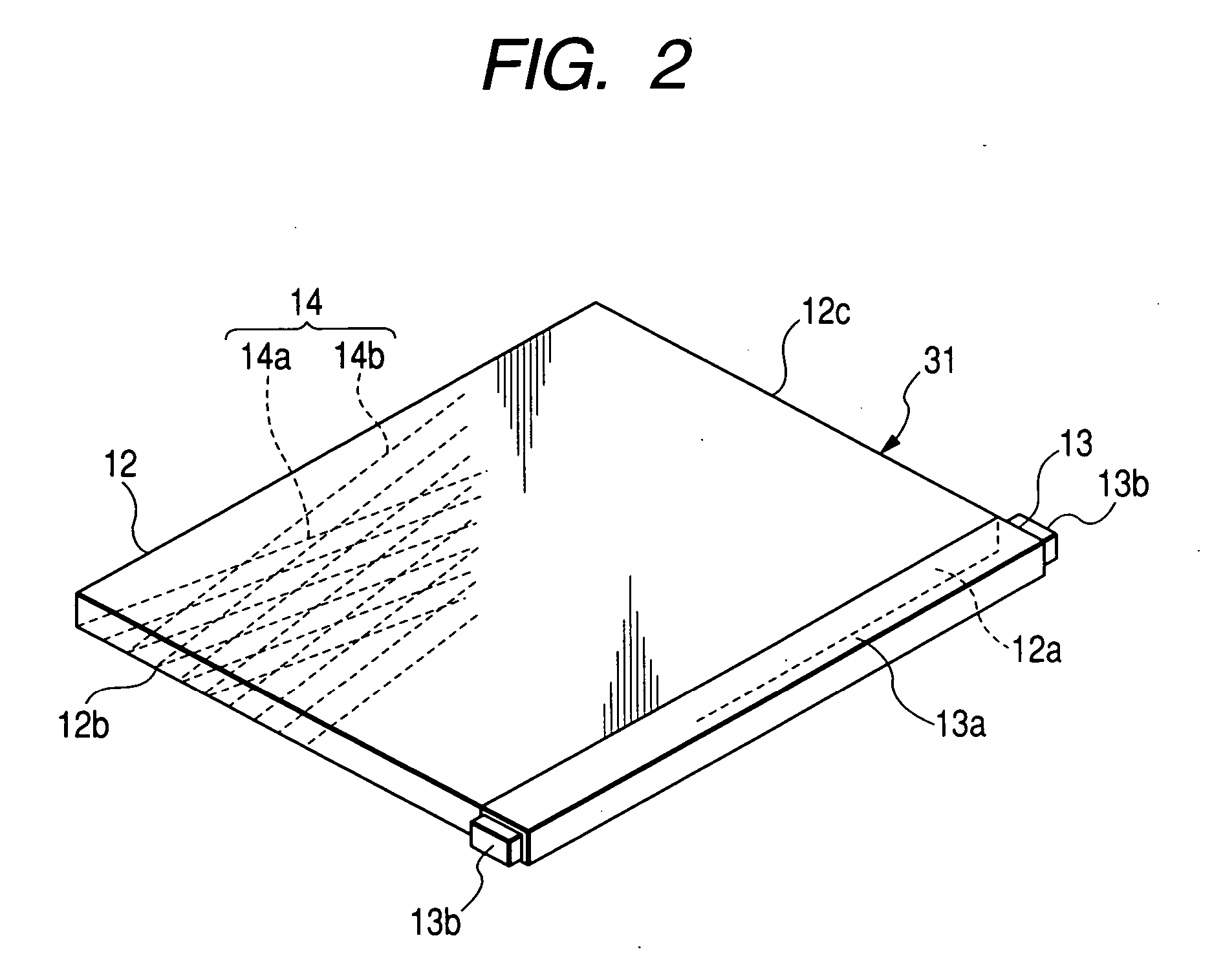
[0034] The applicant of the invention has verified the effects of the surface emitting device of the invention. For the verification, four kinds of light-guiding plates were prepared in which the light emission surfaces had minute prism shapes formed by setting the cross angle θ of the first groove 14a extending in the first direction Ll shown in FIG. 3 and the second groove 14b extending in the second direction L2 in the above-described preparation example to 32°, 46°, 60°, and 90°, respectively. Further, as a comparative example, a related art light-guiding plate was prepared to have the same configuration as the above-described examples, excluding stripe prism shapes (parallel prisms) formed in a direction perpendicular to a propagation direction of light from a light source by easy slopes (slope angle of 2.5°) and steep slopes (slope angle of 50°) so as to form a plurality of grooves, such that the easy slopes were disposed closer to the light source than the steep slopes.

[0035...


PUM


Abstract

At the light emission surface of at light-guiding plate, a first and second grooves are formed. Each of the first grooves has a pair of slope parts, and each slope part has an easy slope and a steep slope. The second grooves intersect the first grooves at predetermined angles. Each of the second grooves has a pair of slope parts, and each slope part has an easy slope and a steep slope. With the first grooves and the second grooves intersecting each other, at the light emission surface, a plurality of minute prisms are formed in flat quadrangular pyramid shapes to be dented toward the surface opposite to the light emission surface of the light-guiding plate.

Description

BACKGROUND OF THE INVENTION [0001] 1. Field of the Invention [0002] The present invention relates to a surface emitting device, which emits planar light by a light-guiding plate, and to a backside illumination device and a liquid crystal display device using the same. [0003] 2. Description of the Related Art [0004] For example, in order to illuminate brightly liquid crystal display panels mounted on cellular phones, mobile game machines, and the like, a surface emitting device using a light-guiding plate with a plurality of minute grooves formed at the surface thereof (See Japanese Unexamined Patent Application Publication No. 2003-257229). The surface emitting device has a configuration in which light from a light source formed adjacent to a side end surface of a flat light-guiding plate is incident on the light-guiding plate and is emitted from a light emission surface of the light-guiding plate. For this reason, at the light emission surface, a plurality of grooves (prisms), each...

Claims


Application Information

Patent Timeline
Patent Type & Authority Applications(United States)
IPC IPC(8): F21V7/04
CPCG02B6/0036G02B6/0053G02B6/0055
Inventor SUGIURA, TAKURO
Owner ALPS ALPINE CO LTD
Why Eureka
Try Eureka