
Scratch and mar resistant PDLC modulator

a modulator and pdlc technology, applied in the field of liquid crystal modulators, can solve the problems of severe curtailment of useful life, inability to use modulators, and inability to meet the needs of users, and achieve superior hardness and toughness, good adhesion, and minimize unnecessary wear.

Active Publication Date: 2006-05-11
ORBOTECH LTD
View PDF1 Cites 5 Cited by
  • Summary
  • Abstract
  • Description
  • Claims
  • Application Information

AI Technical Summary

Benefits of technology

[0011] According to the invention, a PDLC modulator is fabricated using at least one of a selection of specially-formulated UV curable organic hard coatings as a protective layer on the exposed side of polyester (Mylar) film. The hard coatings of various related types show good adhesion on a polyester film substrate, superior hardness and toughness, and have a slippery top surface, which minimizes unnecessary wear. The coating as applied on the modulator surface significantly reduces scratch damage on modulators caused by unexpected particles on the panels under test. In addition, the slip surface will reduce stickiness to particles and therefore also reduce the possibility of panel damage.

Problems solved by technology

Due to the close proximity of components relative to panels under test, PDLC modulator structures are subject to damage in normal use, which severely curtails useful life.
Due to the softness of the polyester film, its surface is prone puncture and scratch damage, so that the modulator lifetime has become an issue.
These damage modes render the modulators useless after relatively short periods of time.
Prior solutions have been developed which have proved inadequate.
The resulting thin film shows weak mechanical strength (which is thus easy to break) when the finished modulator is used in an applicable system.
While this approach could potentially provide a hard but thin surface on the top of modulator, no data related to modulator durability is available.
Moreover, attempts at fabricating such a structure have faced technical challenges, including poor yield.

Method used


Image

  • Scratch and mar resistant PDLC modulator
  • Scratch and mar resistant PDLC modulator

Examples


Embodiment Construction

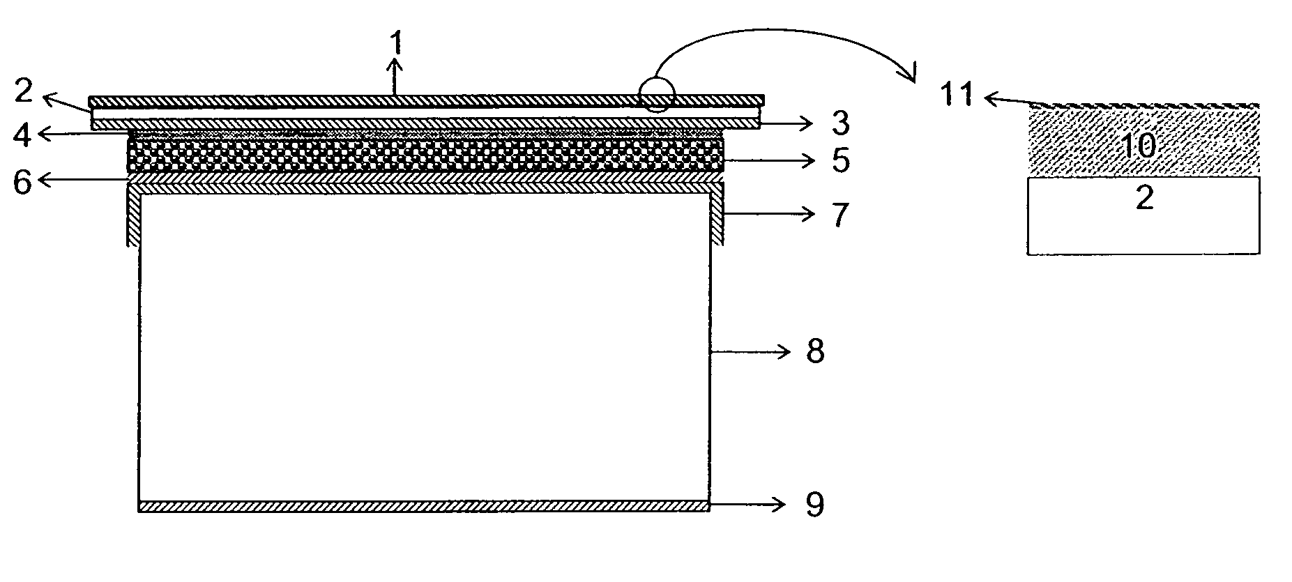
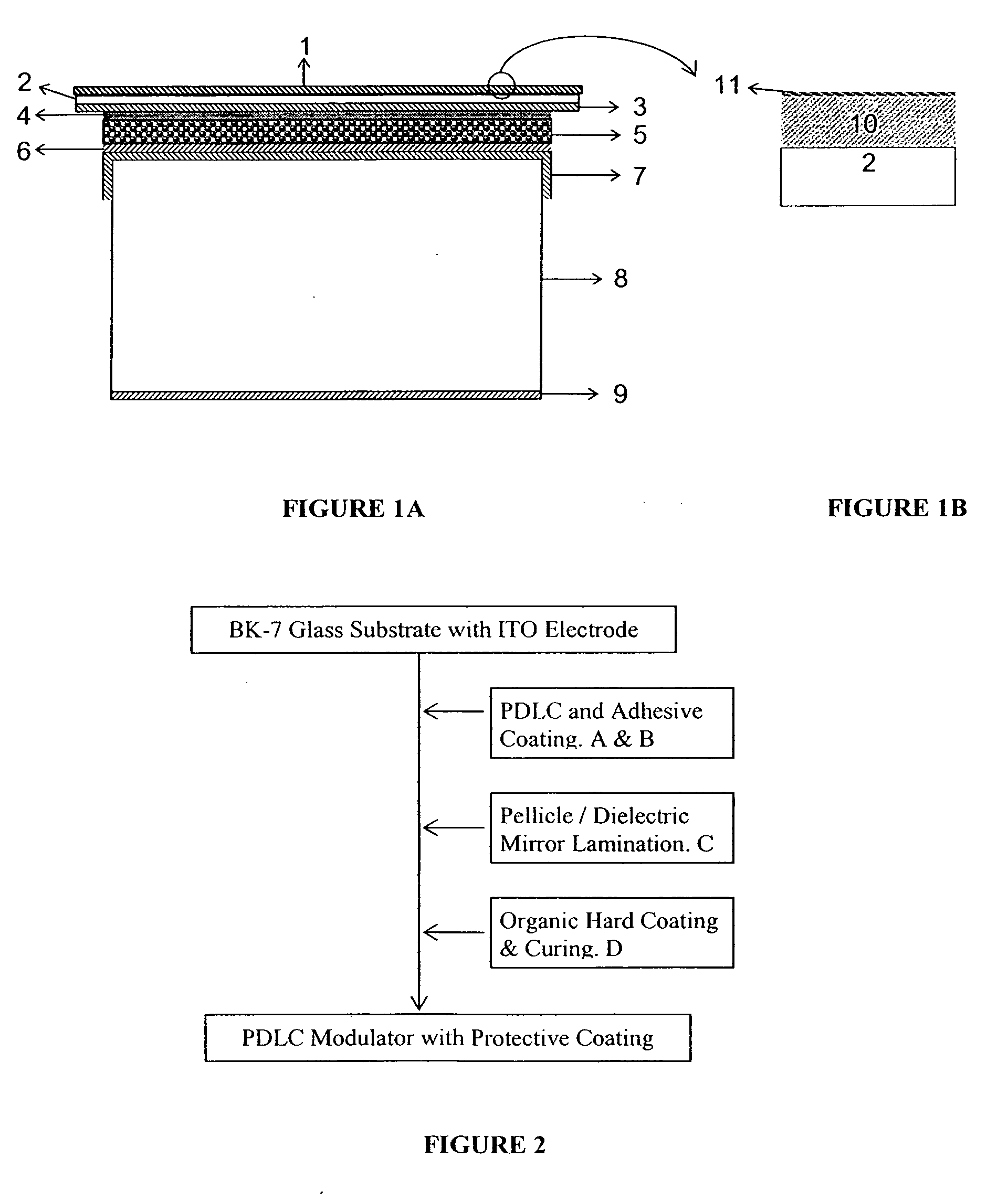
[0015] In accordance with the invention, UV curable organic hard coatings have been formulated and applied as a protective layer on the surface of electro-optical modulators. The coatings show good adhesion to plastic (Mylar) substrate, ≧3H hardness, superior toughness and slippery top surface.

[0016] As shown in FIG. 1A and in greater detail in FIG. 1B, an organic hard coating 1 is placed on an otherwise finished modulator. The organic hard coating 1 comprises a major hard coating 10, has over it a much thinner slip agent layer 11. Specifically, the coating 1 is applied to a polyester film (such as Mylar) 2, which in turn covers and protects a fragile dielectric mirror 3 that is held in place by a water-borne adhesive layer 4 upon the surface of a PDLC layer 5. An insulative layer 6 of silicon dioxide (SiO2) separates the PDLC layer 5 from a transparent electrode 7 of indium tin oxide (ITO) on a glass substrate 8, which is typically BK-7 type optical glass. An antireflective coatin...


PUM

PropertyMeasurementUnit
Electrical resistanceaaaaaaaaaa
Adhesion strengthaaaaaaaaaa

Abstract

A PDLC modulator is fabricated using at least one of a selection of specially-formulated UV curable organic hard coatings as a protective layer on the exposed side of polyester (Mylar) film. The hard coatings of various related types show good adhesion on a polyester film substrate, superior hardness and toughness, and have a slippery top surface, which minimizes unnecessary wear. The coating as applied on the modulator surface significantly reduces scratch damage on modulators caused by unexpected particles on the panels under test. In addition, the slip surface will reduce stickiness to particles and therefore also reduce the possibility of panel damage.

Description

CROSS-REFERENCES TO RELATED APPLICATIONS [0001] NOT APPLICABLE STATEMENT AS TO RIGHTS TO INVENTIONS MADE UNDER FEDERALLY SPONSORED RESEARCH OR DEVELOPMENT [0002] NOT APPLICABLE REFERENCE TO A “SEQUENCE LISTING,” A TABLE, OR A COMPUTER PROGRAM LISTING APPENDIX SUBMITTED ON A COMPACT DISK. [0003] NOT APPLICABLE BACKGROUND OF THE INVENTION [0004] This invention relates to liquid crystal modulators and more particularly to polymer dispersed liquid crystal (PDLC) modulator structures. (PDLC may be a mixture of hydroxyl polyacrylate with the TL-series of liquid crystal, where the hydroxyl group is crosslinked by polyisocyanate.) [0005] PDLC modulators are used to test thin film transistors in the liquid crystal display (LCD) industry. Modulator lifetime improvement is one of the major objectives in PDLC modulator research and development. Due to the close proximity of components relative to panels under test, PDLC modulator structures are subject to damage in normal use, which severely cu...

Claims


Application Information

Patent Timeline
IPC IPC(8): G02F1/00
CPCG02F1/1334Y10T428/10G02F2201/50G02F1/1341C09K2323/00B82Y40/00
Inventor CHEN, XIANHAI
Owner ORBOTECH LTD
Learn More