
Magnetic toner and image forming method using the same

a technology which is applied in the field of magnetic toner and image forming method, can solve the problems of increasing image formation speed and miniaturization, affecting the quality of formed images, etc., and achieves the effect of quick rise and easy charging amoun

Active Publication Date: 2006-04-13
KYOCERA DOCUMENT SOLUTIONS INC
View PDF5 Cites 4 Cited by
  • Summary
  • Abstract
  • Description
  • Claims
  • Application Information

AI Technical Summary

Benefits of technology

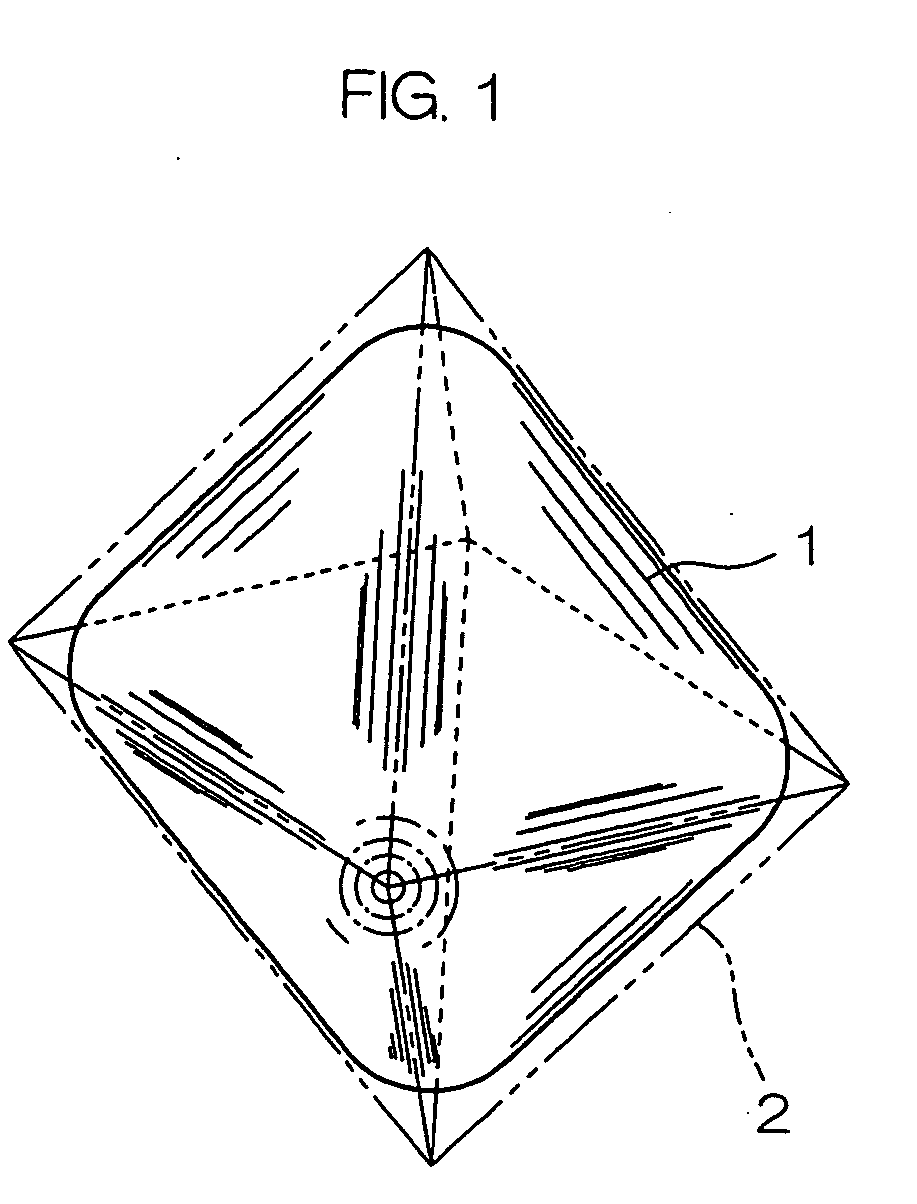
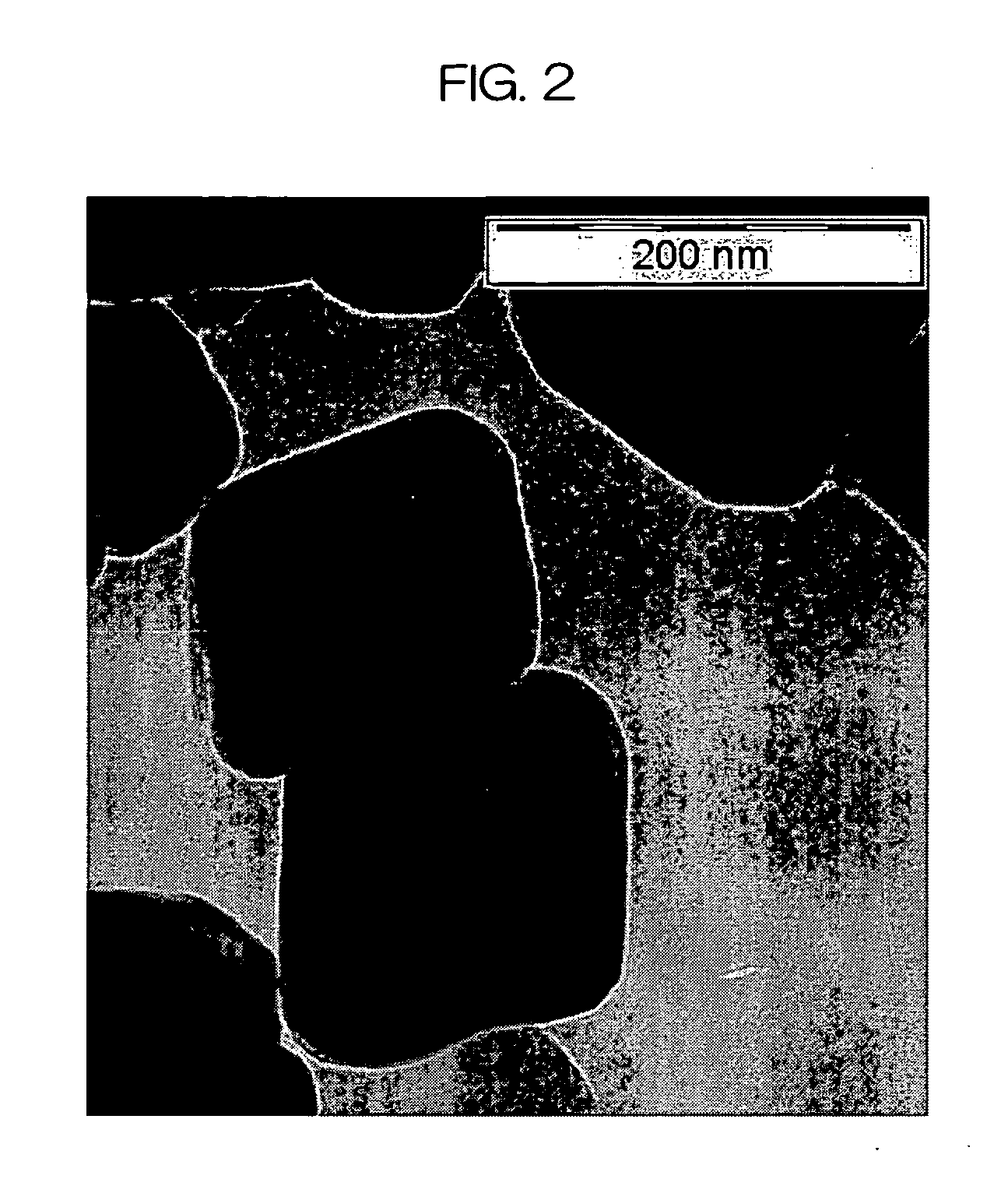
The present invention provides magnetic toner that has both good charging properties and prevents charge-up. The magnetic powder used in the toner has a unique shape that allows for easy charging and prevents leakage of charges. The magnetic powder has an average particle diameter of 0.01 to 0.50 μm and is in the form of an octahedron, which has curved surfaces and does not have points that can easily discharge charges. The use of this magnetic powder results in a more uniform dispersion in the binder resin, preventing variations in the dispersed state of the magnetic powder.

Problems solved by technology

In a high-speed machine mainly adaptable to business applications where the increase in image formation speed is required, the resolution and the quality of a formed image are liable to decrease as the printing speed increases.
Currently in the magnetic toner generally employed, however, the requirements have not been sufficiently satisfied in the present circumstances in the above-mentioned currents, that is, increase in image formation speed and miniaturization.
In the magnetic toner using the polyhedral magnetic powder, however, pointed vertexes or pointed edges between adjacent faces of the magnetic powder are exposed to surfaces of toner particles and charges are easily discharged therefrom, so that the charges are liable to leak.
The polyhedral magnetic powder is low in fluidity and is inferior in dispersibility to binder resin.
Accordingly, it is difficult to uniformly disperse the magnetic powder in the binder resin.
In the magnetic toner using the polyhedral magnetic powder, therefore, the charging amount does not easily rise quickly, and the charging amount itself is small.
As a result, image defects such as decrease in image density and occurrence of fogging are liable to occur.
Particularly under environments, where charging is difficult, such as high-temperature and high-humidity environments, the above-mentioned image defects are liable to further occur.
In the magnetic toner using the spherical magnetic powder, however, charges are conversely too easily stored.
When the charge-up occurs, image defects represented by decrease in image density rather easily occurs.
Accordingly, the charges are liable to leak from the magnetic toner, so that image defects such as decrease in image density and occurrence of fogging may occur.

Method used


Image

  • Magnetic toner and image forming method using the same
  • Magnetic toner and image forming method using the same
  • Magnetic toner and image forming method using the same

Examples


example 1

[0149]

[0150] 845 mass parts of styrene, 155 mass parts of n-butyl acrylate, and 8.5 mass parts of di-tert-butyl peroxide were dissolved in 125 mass parts of xylene under a nitrogen atmosphere, to prepare a solution.

[0151] 300 mass parts of xylene was put in a reaction chamber in which a thermometer, an agitating machine, a nitrogen introducing pipe, and a reflux condenser are connected to the reaction chamber, the previously prepared solution was dropped into the reaction chamber in three hours while heating the reaction chamber to maintain the liquid temperature at 170° C. while continuously introducing nitrogen from the nitrogen introduction pipe, the solution was further agitated for one hour at 170° C. after the dropping was terminated, and a solvent was then removed, to prepare a styrene-n-butyl acrylate copolymer serving as binder resin.

[0152]

[0153] Used as the magnetic powder is magnetic powder having an average particle diameter of 0.22 μm, composed of magnetite containing...


PUM


Abstract

Magnetic toner involves magnetic powder 1 having the particle shape of an octahedron 2 that is a convex polyhedron surrounded by eight triangles as a basis, each of the vertexes and edges of the octahedron being in a curved surface shape, and having a portion 3 that can be taken as a straight line on the outer periphery of its projected image. Therefore, the magnetic toner is superior in both two contradictory properties, that is the property of making it easy for a charging amount to quickly rise as well as improving the charging amount and the property of making it difficult for charge-up to occur, thereby making it possible to form a good image under a wide environment. In an image forming method, an electrostatic latent image is developed into a toner image by a magnetic one-component jumping developing method using the magnetic toner.

Description

BACKGROUND OF THE INVENTION [0001] The present invention relates to a magnetic toner and an image forming method using the same. [0002] In image forming apparatuses such as laser printers, electrostatic copying machines, plain paper facsimiles, and their complex machines utilizing electrophotographic methods, electrostatic recording methods, or electrostatic printing methods, a surface of a latent image holding member is uniformly charged by charging means, and is then exposed by exposure means such as semiconductor lasers or light-emitting diodes, to form an electrostatic latent image on the surface, and the electrostatic latent image is then developed into a toner image by developing means. The toner image is then directly transferred to a surface of a material to be printed such as paper by transfer means or is transferred to a surface of an intermediate transfer member, is then transferred again on the surface of the material to be printed such as paper, and is then fixed to the...

Claims


Application Information

Patent Timeline
Patent Type & Authority Applications(United States)
IPC IPC(8): G03G9/083
CPCG03G9/081G03G9/0833G03G9/0834G03G9/0836G03G9/0837G03G9/0838G03G9/0839
Inventor NAKAYAMA, YUKINORITERAMOTO, KOUZOUMIZUHATA, HIROSHISATOU, KOUSUKE
Owner KYOCERA DOCUMENT SOLUTIONS INC
Learn More