
Vehicle air conditioning device

a technology of vehicle air conditioner and heat pump, which is applied in the direction of circuit arrangement, transportation and packaging, electrical generators, etc., can solve the problems of deterioration, battery malfunction, battery breakage, etc., and achieve the effect of accurate judgment of the need for temperature regulation, easy rise, and improved energy saving and reliability

Active Publication Date: 2022-02-03
SANDEN CORP
View PDF2 Cites 4 Cited by
  • Summary
  • Abstract
  • Description
  • Claims
  • Application Information

AI Technical Summary

Benefits of technology

The present invention relates to a vehicle air conditioning device which controls the temperature of an object inside a vehicle. It uses a compressor to compress refrigerant, an indoor heat exchanger to exchange heat with the air in the vehicle, an outdoor heat exchanger to perform the same function, and a control device to manage the device. The control device adjusts the temperature of the object based on the change in the indicator that indicates the temperature of the object. By using the change in the indicator, the device accurately determines if the object needs to be cooled or heated and saves energy and improves reliability. The control device also takes into account the influence of the outdoor air temperature and the self-heating of the battery during charging to start cooling the battery at an earlier stage and prevent abnormal temperature rise during charging.

Problems solved by technology

On the other hand, for example, when the battery is charged and discharged in an environment where the temperature becomes high due to self-heating or the like due to its charging and discharging, deterioration will progress, and eventually there is a risk that the battery malfunctions to break.
In addition, the charge and discharge performance is reduced even under a low temperature environment.

Method used


Image

  • Vehicle air conditioning device
  • Vehicle air conditioning device
  • Vehicle air conditioning device

Examples


Embodiment Construction

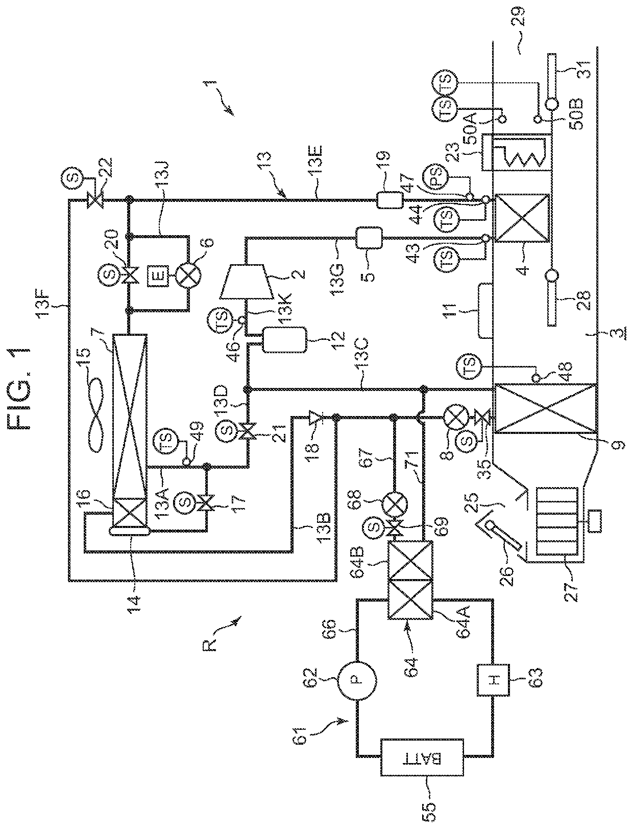
[0093]Hereinafter, embodiments of the present invention will be described in detail with reference to the drawings. FIG. 1 shows a constitutional diagram of a vehicle air conditioning device 1 of an embodiment of the present invention. A vehicle of the embodiment to which the present invention is applied is an electric vehicle (EV) in which an engine (internal combustion engine) is not mounted, and which runs with a motor for running (electric motor and not shown in the drawing) which is driven by being supplied with power charged in a battery 55 mounted in the vehicle. A compressor 2 to be described later in the vehicle air conditioning device 1 of the present invention is also driven by the power supplied from the battery 55.

[0094]That is, in the electric vehicle which is not capable of performing heating by engine waste heat, the vehicle air conditioning device 1 of the embodiment changes and executes respective operation modes of a heating mode, a dehumidifying and heating mode,...


PUM


Abstract

A vehicle air conditioning device is provided which is capable of accurately judging the need for temperature regulation of an object of temperature regulation mounted in a vehicle and efficiently performing temperature regulation. A compressor 2 to compress a refrigerant, an indoor heat exchanger (radiator 4 and heat absorber 9) for exchanging heat between air supplied to a vehicle interior and the refrigerant, an outdoor heat exchanger 7 disposed outside the vehicle interior, and a control device 11 are provided to perform air conditioning of the vehicle interior. An equipment temperature adjusting device 61 for adjusting the temperature of the object of temperature regulation mounted in the vehicle is provided. The control device controls the equipment temperature adjusting device 61 on the basis of a gradient (ΔTw) of a change in an index indicating the temperature of the object of temperature regulation.

Description

CROSS-REFERENCE T0 RELATED APPLICATIONS[0001]This application is a U.S. National Stage Patent Application under 35 U.S.C. § 371 of International Patent Application No. PCT / JP2019 / 036222, filed on Sep. 13, 2019, which claims the benefit of Japanese Patent Application No. 2018-191141, filed on Oct. 9, 2018, the disclosures of each of which are incorporated herein by reference in their entirety.TECHNICAL FIELD[0002]The present invention relates to an air conditioner of a heat pump system which conditions air of a vehicle interior of a vehicle, and more particularly to a vehicle air conditioning device capable of adjusting the temperature of an object of temperature regulation such as a battery mounted in a vehicle.BACKGROUND ART[0003]Due to actualization of environmental problems in recent years, vehicles such as electric vehicles and hybrid cars each of which drives a motor for running by power supplied from a battery mounted in the vehicle have spread. Further, as an air conditioning...

Claims


Application Information

Patent Timeline
Patent Type & Authority Applications(United States)
IPC IPC(8): B60H1/00B60H1/32
CPCB60H1/00278B60H1/00914B60H1/00792B60H1/00921B60H1/3213B60H1/32281B60H2001/00949B60H2001/00928B60H2001/3257B60H2001/3258B60H2001/3263B60H2001/3264B60H2001/00307H01M10/625H01M10/633H01M10/651H01M10/613H01M10/615H01M10/6563H01M10/6568H01M10/6571H01M10/6556H01M10/663H01M10/617Y02E60/10B60H1/2225B60H2001/3252B60H2001/326H02J7/007192Y02T10/70
Inventor MIYAKOSHI, RYO
Owner SANDEN CORP
Learn More