
Optical transmitter

a technology of optical transmitters and transmitters, applied in the field of optical transmitters, can solve the problems of increasing the current to maintain the optical output power, increasing the forward bias voltage, and increasing the conversion efficiency of electrical to optical signals. achieve the effect of precise and stable control of the emission wavelength of the optical transmitter

Inactive Publication Date: 2006-04-06
SUMITOMO ELECTRIC IND LTD
View PDF2 Cites 13 Cited by
  • Summary
  • Abstract
  • Description
  • Claims
  • Application Information

AI Technical Summary

Benefits of technology

The present invention relates to an optical transmitter with a laser diode (LD) that can adjust its emission wavelength to compensate for changes in ambient temperature. The optical transmitter includes a temperature sensor, a thermo-electric device, a first generator, a second generator, and a temperature controller. The first generator generates a reference temperature, while the temperature controller controls the temperature of the LD to match the reference temperature. The second generator generates a correction temperature based on the ambient temperature and compensates for any thermal tracking error by adjusting the temperature of the LD. The optical transmitter also includes a bias driver for providing a bias current to the LD and a lookup table for storing the correction temperature with respect to the ambient temperature. The invention allows for precise and stable control of the LD's emission wavelength even at extreme temperatures.

Problems solved by technology

The long-term deterioration of the LD increases the forward bias voltage thereof because the resistance of the active layer increases.
Moreover, the conversion efficiency from electrical to optical signals also degrades as the long-term deterioration of the LD, which increases the current to maintain the optical output power.
Accordingly, the power consumption of the LD increases, which raises the temperature of the active layer and shifts the emission wavelength thereof.
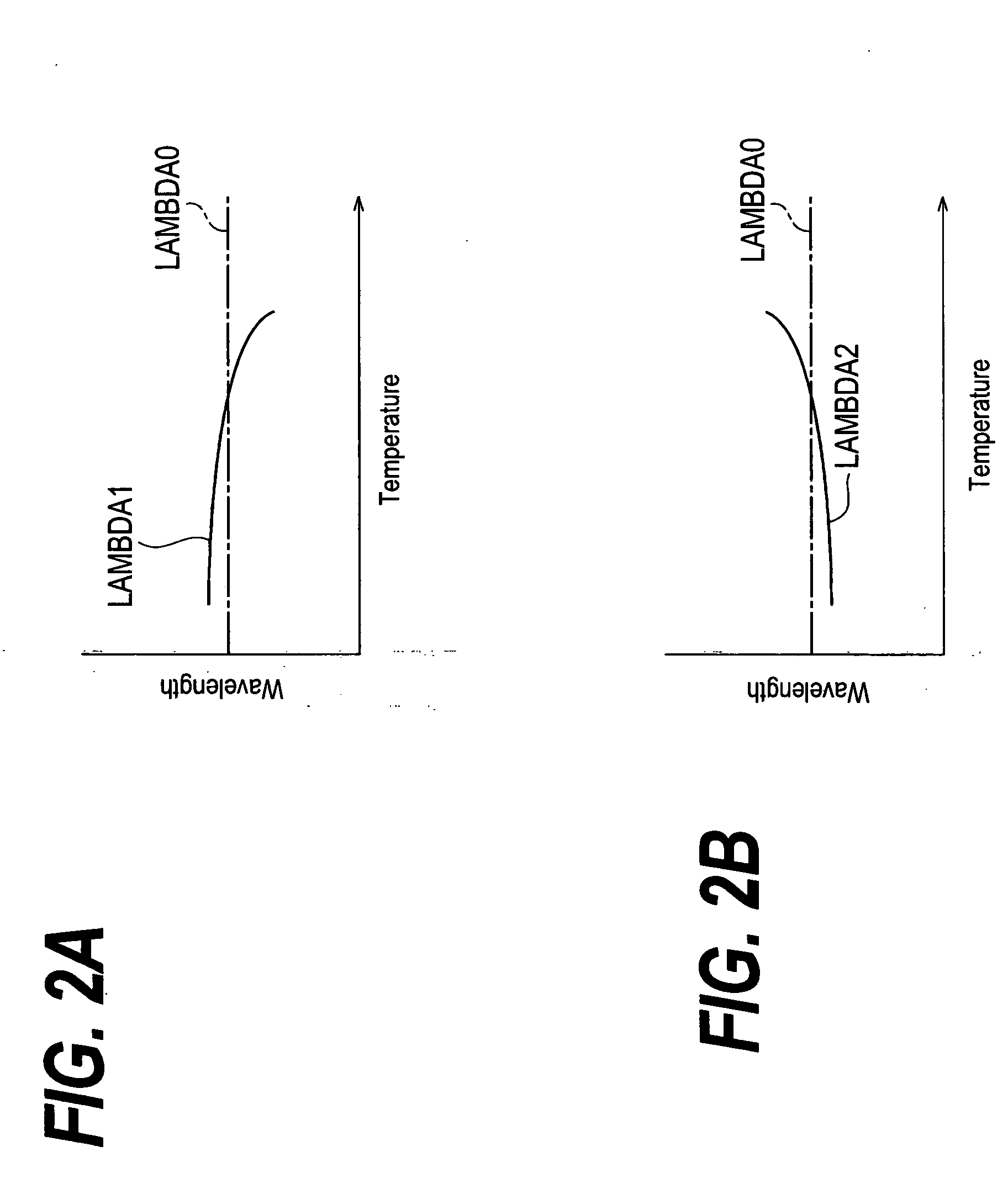
However, these controllers disclosed in patents mentioned above only control the target temperature of the LD to compensate the long-term deterioration, not compensates the tracking error itself.

Method used


Image

  • Optical transmitter
  • Optical transmitter
  • Optical transmitter

Examples


Embodiment Construction

[0021] The present invention will be easily understood by taking the description below into account referring to accompanying drawings. Next, preferred embodiments of the invention will be described as referring to drawings. In the description, the same symbol or numeral will refer to the same element if possible.

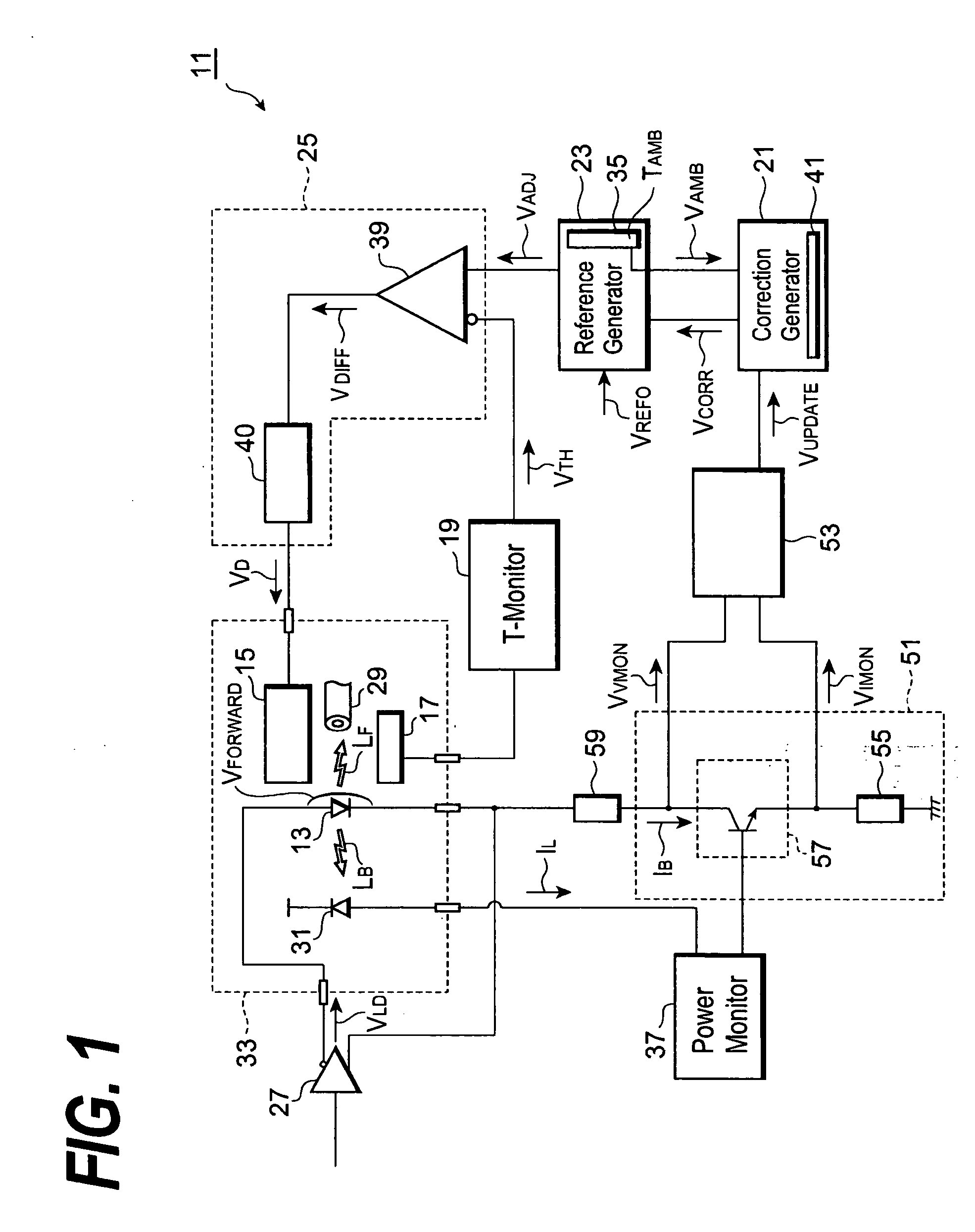
[0022]FIG. 1 is a block diagram of an optical transmitter according to the first embodiment of the invention. The optical transmitter 11 comprises a laser diode (LD) 13, a thermo-electric device 15 (hereinafter denoted as TEC), a temperature sensor 17, a block 19 for monitoring the temperature, a first generator 21 for a correction signal, a second generator 23 for a reference signal, and a temperature controller 25. The LD 13 generates optical outputs (LF, LB) by responding to a driving signal VLD provided from the LD-Driver 27. A portion LF of the output enters an optical fiber 29, while another portion LB enters a light-receiving device 31 for monitoring the optical out...


PUM

PropertyMeasurementUnit
temperatureaaaaaaaaaa

Abstract

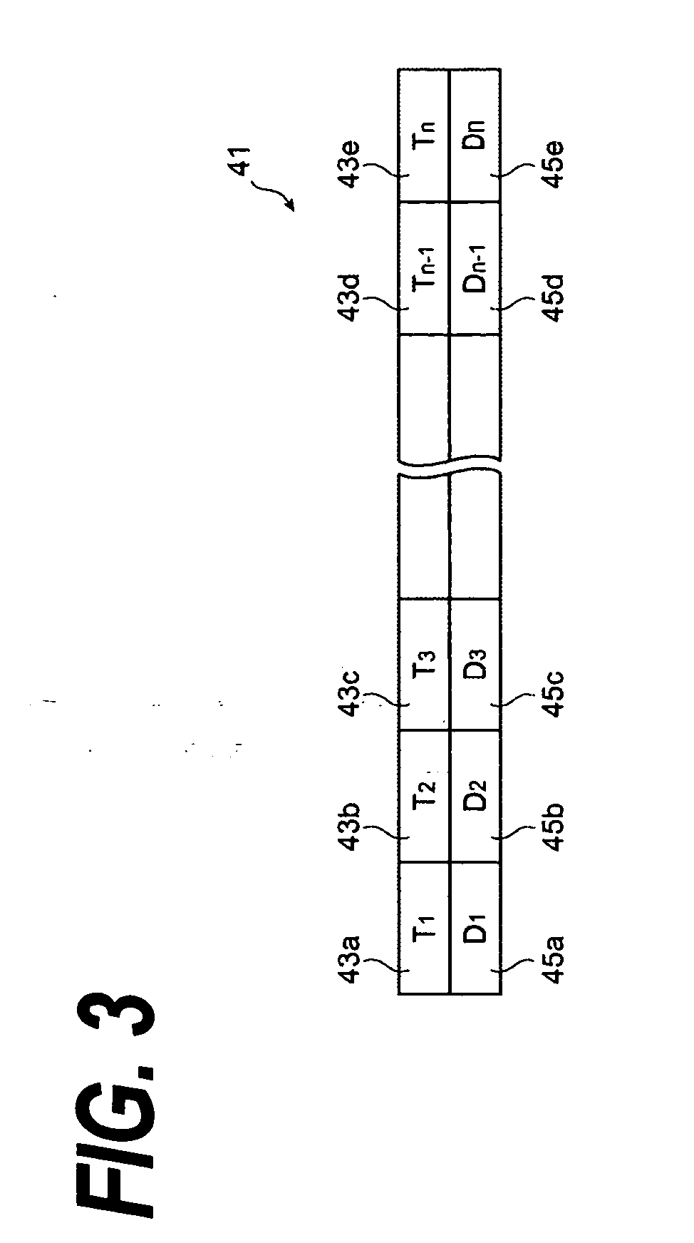
The present invention provides an optical transmitter that compensates the thermal tracking error. The transmitter comprises a temperature feedback loop including temperature controller that controls the temperature of the laser diode to coincide with the reference temperature by the thermo-electric device. The reference temperature reflects the thermal tracking error that depends on the ambient temperature and that of the target temperature of the laser diode. The transmitter installs a lookup table for providing the reference temperature. The lookup table is rewritten taking the long-term deterioration of the laser diode into account, which is reflected in the increase of the bias current and the forward voltage of the laser diode.

Description

BACKGROUND OF THE INVENTION [0001] 1. Field of the Invention [0002] The present invention relates to an optical transmitter. [0003] 2. Related Prior Art [0004] Japanese patent published as H11-163462 has disclosed a controller to stabilize the emission wavelength of the laser diode, hereinafter denoted as LD. This controller corrects the drift of the emission wavelength, which is due to the increase and the decrease of the driving current fort the LD, in a long period to stabilize the wavelength thereof in a superior precision. The controller includes a current detector, a normalizer, and a reference generator. The current detector detects the magnitude of the driving current for the LD, which is adjusted by the control circuit for the optical output. The normalizer normalizes the current detected by the current detector. The reference generator outputs a target temperature for the LD, which depends on the normalized current. The controller further includes a temperature sensor that...

Claims


Application Information

Patent Timeline
Patent Type & Authority Applications(United States)
IPC IPC(8): G02F1/295
CPCH01S5/0612H01S5/0617H01S5/0687H01S5/02415H01S5/06804
Inventor KAWAGISHI, TORU
Owner SUMITOMO ELECTRIC IND LTD
Learn More