
Light emitting diodes exhibiting both high reflectivity and high light extraction

Inactive Publication Date: 2006-04-06
GOLDENEYE
View PDF20 Cites 110 Cited by
  • Summary
  • Abstract
  • Description
  • Claims
  • Application Information

AI Technical Summary

Benefits of technology

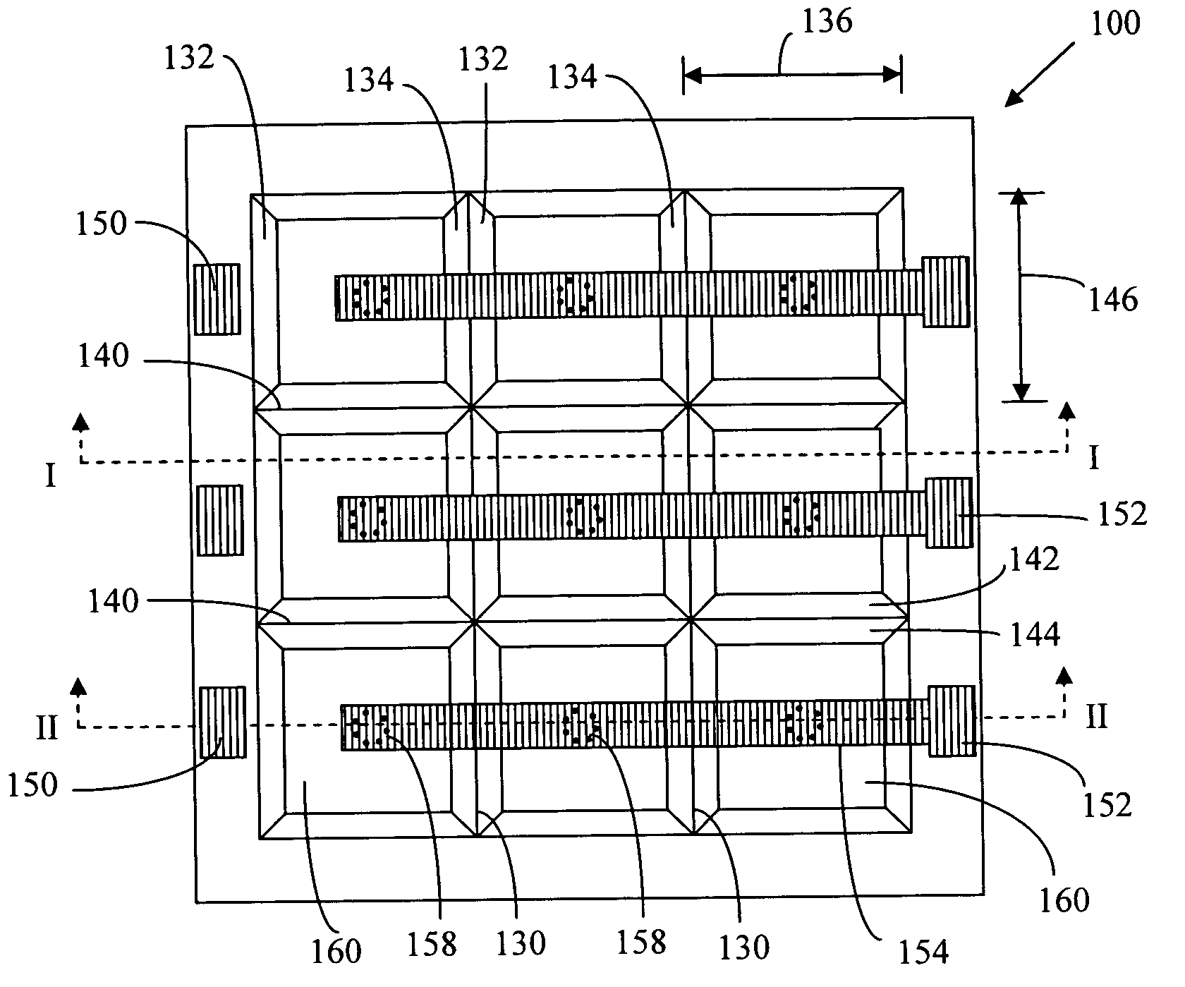
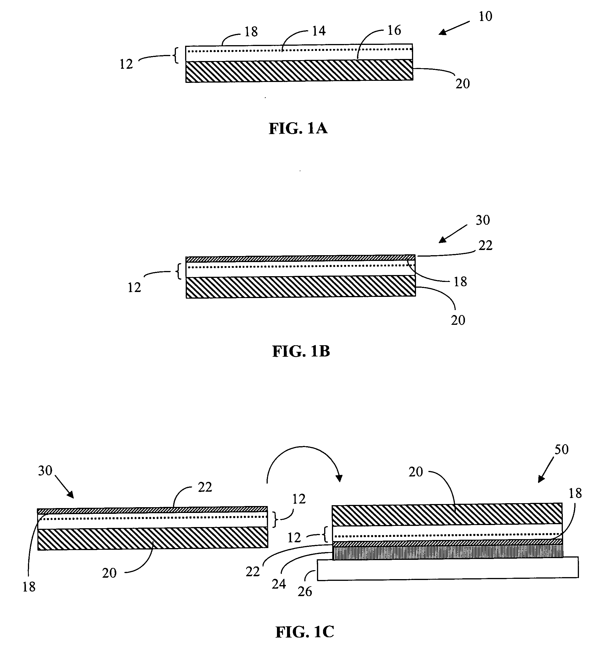
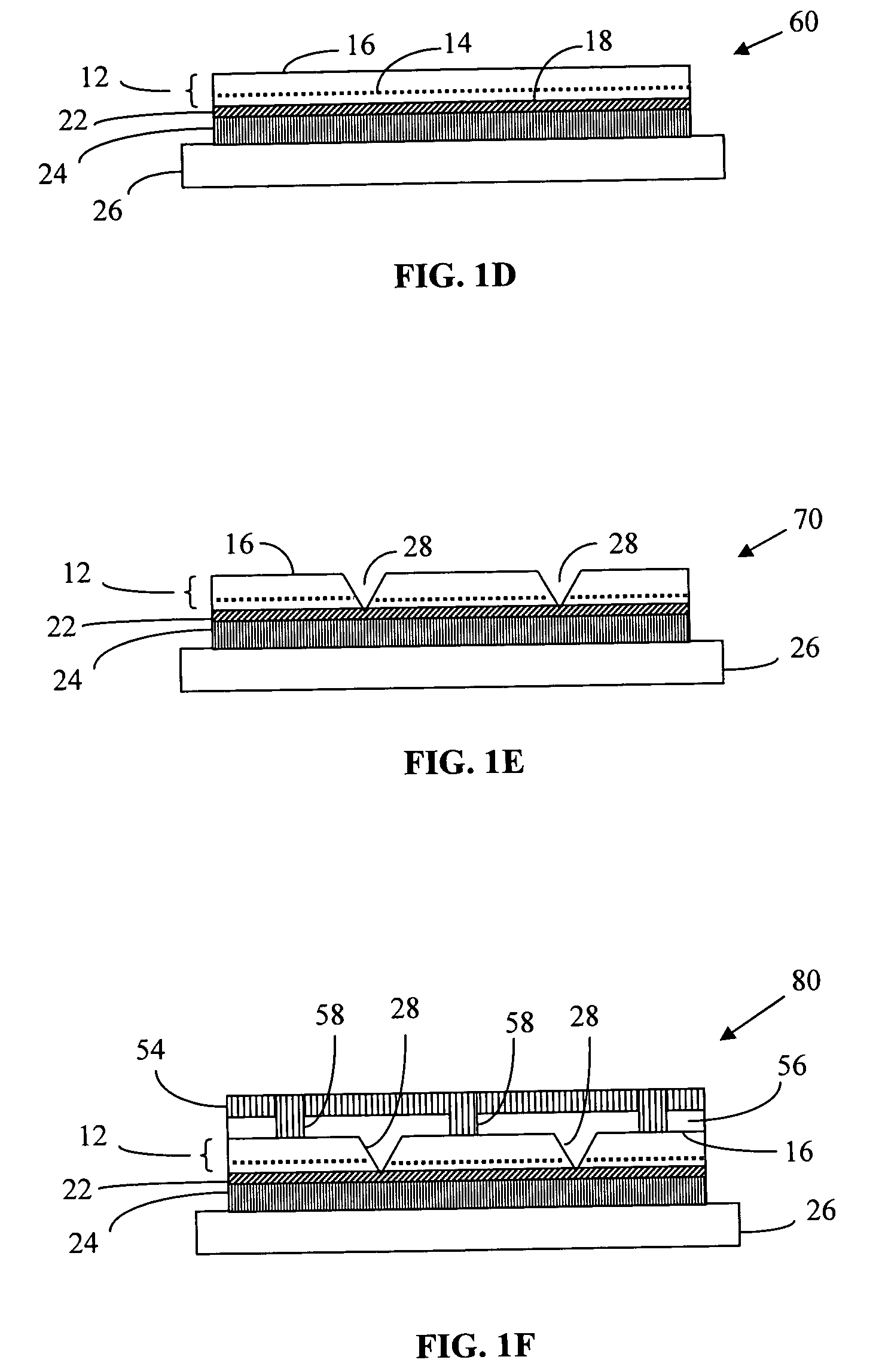
[0019] One embodiment of this invention is a light emitting diode that exhibits high reflectivity to incident light and high extraction efficiency for internally generated light. The light emitting diode includes a reflecting layer that reflects both the incident light and the internally generated light. A multi-layer semiconductor structure is in contact with the reflecting layer. The multi-layer semiconductor structure has an absorption coefficient alpha and includes an active layer that emits the internally generated light. An array of light extracting elements extends at least part way through the multi-layer semiconductor structure and improves the extraction efficiency for internally generated light. The light extracting elements are trenches, holes, ridges or etched strips that have angled sidewalls. The light extracting elements are separated by a fractional distance relative to the absorption coefficient alpha.
[0020] Another embodiment of this invention is an illumination system incorporating a light emitting diode that exhibits high reflectivity to incident light and high extraction efficiency for internally generated light. The illumination system also comprises a light recycling means. The light recycling means can be a reflecting polarizer, a light recycling envelope or a wavelength conversion material. A portion of the light emitted by the light emitting diode is recycled back to the light emitting diode by the reflecting polarizer, the light recycling envelope or the wavelength conversion material, thereby increasing the effective brightness of the light emitting diode. The high reflectivity of the light emitting diode improves the overall light output efficiency of the illumination system.

Problems solved by technology

However, one issue that currently restricts LED deployment is low light output efficiency.
For example, increasing the refractive index of the LED relative to its surroundings will decrease the light extraction efficiency.
Increasing the absorption coefficient alpha of the semiconductor layers will decrease the light extraction efficiency.
The absorption coefficient of the GaN-based semiconductor layers is sometimes difficult to determine accurately because of light scattering that is also present in the materials.
The substrate adds to the thickness of the LED die and can reduce the overall light extraction efficiency of the array.
U.S. Pat. No. 6,410,942 and other patents on light extraction do not disclose how to make LEDs or arrays of micro-LEDs that are highly reflective.
Thirdly, if a light source is comprised of both an LED and a phosphor that converts at least a part of the LED emitted light into another wavelength, the phosphor can reflect some of the emitted light back to the LED.
If the LED has poor reflectivity, some of the reflected light will be absorbed by the LED and reduce the overall efficiency of the light source.
In comparison to surfaces that have a high density of light extracting elements, smooth LED surfaces that do not have light extracting elements have poor light extraction efficiency but can be good light reflectors.
Improving one of the two quantities tends to degrade the other quantity.
For example, GaN-based LEDs that have a silicon carbide substrate are usually poor light reflectors with an overall reflectivity of less than 60%.
For example, the top metal electrodes and wire bonds on many LEDs contain materials such as gold that have relatively poor reflectivity.

Method used


Image

  • Light emitting diodes exhibiting both high reflectivity and high light extraction
  • Light emitting diodes exhibiting both high reflectivity and high light extraction
  • Light emitting diodes exhibiting both high reflectivity and high light extraction

Examples


example 1

[0162] A non-sequential ray tracing computer program was used to model the light extraction efficiency and the reflectivity of GaN LEDs that incorporated arrays of trenches for enhanced light extraction. The computer model included the effects of Fresnel reflections at the principal interfaces where the refractive index changed and included the effects of absorption in the semiconductor materials. A 4 micron thick GaN multi-layer semiconductor structure was modeled as a uniform single layer that had an absorption coefficient alpha of 50 cm−1. One side of the multi-layer semiconductor structure was coated with a metal reflecting layer. The reflectivity R(metal) of the reflecting layer was 0.95 or 95%. The opposite side of the GaN layer was the output side of the LED and was in contact with air having a refractive index of 1.0. The LED incorporated two arrays of trenches that had either positive or negative sidewall angles. The first set of trenches was perpendicular to the second set...

example 2

[0166] Example 2 is the same as Example 1 except that in Example 2 the output surface of the LED was embedded in a transparent material that had a refractive index of 1.50. The detector in this computer model was also embedded in the same transparent material and there was no air interface between the emitter and the detector. The model calculated the LED light extraction efficiency and reflectivity that would be measured inside a light recycling envelope that was filled with the transparent material.

[0167] The results are shown in FIG. 11. Compared to Example 1, embedding the LED in a material with a refractive index of 1.50 improved both the light extraction efficiency 1110 and the reflectivity 1120 of the LED. The reflectivity 1120 was greater than 77% for all angles and the light extraction efficiency 1110 was greater than 70% for some sidewall angles. However, the calculated light extraction efficiencies would be lower if the detector were in air and there were an air interfac...

example 3

[0168] In Example 3, a non-sequential ray tracing program was used to model the light extraction efficiency and the reflectivity of GaN LEDs that incorporated two perpendicular arrays of trenches. The sidewall angle of the trenches was fixed at +48 degrees and the trench spacing L was varied from 25 microns to 300 microns. A sidewall angel of +48 degrees corresponded to a maximum trench half-width of 4.5 microns (full width of 9 microns) when the multi-layer semiconductor structure was 4 microns thick. The trenches extended all the way through the GaN layer but did not extend into the metal reflecting layer. The resulting output surface of the LED was an array of square mesas. As in Example 1, the 4 micron thick GaN multi-layer semiconductor structure was modeled as a uniform single layer that had an absorption coefficient alpha of 50 cm−1. One side of the multi-layer semiconductor structure was coated with a metal reflecting layer. The reflectivity R(metal) of the reflecting layer ...


PUM


Abstract

The invention is a light emitting diode that exhibits high reflectivity to incident light and high extraction efficiency for internally generated light. The light emitting diode includes a reflecting layer that reflects both the incident light and the internally generated light. A multi-layer semiconductor structure is deposited on the reflecting layer. The multi-layer semiconductor structure has an active layer that emits the internally generated light. An array of light extracting elements extends at least part way through the multi-layer semiconductor structure and improves the extraction efficiency for internally generated light. The light extracting elements can be an array of trenches, an array of holes, an array of ridges or an array of etched strips. The light emitting diode improves the efficiency of light recycling illumination systems.

Description

CROSS REFERENCES TO RELATED APPLICATIONS [0001] This application is related to U.S. patent application Ser. No. 10 / 445,136 entitled “ILLUMINATION SYSTEMS UTILIZING HIGHLY REFLECTIVE LIGHT EMITTING DIODES AND LIGHT RECYCLING TO ENHANCE BRIGHTNESS,” to U.S. patent application Ser. No. 10 / 814,043 entitled “ILLUMINATION SYSTEMS UTILIZING LIGHT EMITTING DIODES AND LIGHT RECYCLING TO ENHANCE OUTPUT RADIANCE” and to U.S. patent application Ser. No. 10 / 814,044 entitled “ILLUMINATION SYSTEMS UTILIZING MULTIPLE WAVELENGTH LIGHT RECYCLING,” all of which are herein incorporated by reference. [0002] This application is also related to U.S. patent application Ser. No. ______ entitled “LIGHT RECYCLING ILLUMINATION SYSTEMS UTILIZING LIGHT EMITTING DIODES” and U.S. patent application Ser. No. ______ entitled “LIGHT RECYCLING ILLUMINATION SYSTEMS HAVING RESTRICTED ANGULAR OUTPUT,” all of which are filed concurrently with this application and are herein incorporated by reference.TECHNICAL FIELD [0003]...

Claims


Application Information

Patent Timeline
IPC IPC(8): H01L33/00H01L33/08H01L33/20H01L33/50
CPCH01L33/0079H01L33/08H01L33/20H01L33/502H01L33/507H01L33/0093
Inventor BEESON, KARL W.ZIMMERMAN, SCOTT M.
Owner GOLDENEYE
Learn More