
Hydrogen separation membrane and process for producing the same

a technology of hydrogen separation membrane and process, applied in the field of metal foil, can solve the problems of low ductility of vanadium alloy foil and niobium alloy foil formed through rolling, increasing production cost, and low ductility of palladium, and achieve excellent resistance to hydrogen embrittlement and hydrogen permeability

Inactive Publication Date: 2006-04-06
FUKUKA METAL FOIL & POWDER CO LTD
View PDF4 Cites 9 Cited by
  • Summary
  • Abstract
  • Description
  • Claims
  • Application Information

AI Technical Summary

Benefits of technology

[0010] A hydrogen separation membrane according to the present invention is made of an amorphous niobium alloy that is formed of 5 to 65 atomic % of at least one or more types which are selected from a group consisting of Ni, Co and Mo as a first additive element, 0.1 to 60 atomic % of at least one or more types which are selected from a group consisting of V, Ti, Zr, Ta and Hf as a second additive element, and the remaining portion of Nb as an indispensable constituent element. Such a niobium alloy is excellent in resistance to hydrogen embrittlement and hydrogen permeability, and is useful as a membrane of a hydrogen refining unit.

Problems solved by technology

Though palladium alloy foils have excellent hydrogen permeability, palladium is relatively expensive, and alternative products made of a material that is cheaper than palladium alloy foils have been in demand.
However, all of the alloys that are described in the above patent documents lack rolling properties, and specific rolling conditions and repeated annealing processing will be required in order to make such alloy foils in accordance with a rolling formation method, raising the cost of production.
In addition, vanadium alloy foils and niobium alloy foils that have been formed through rolling have low ductility and lack processability and durability.
Here, in terms of a niobium alloy foil, in order to enhance resistance to hydrogen embrittlement, the addition of Ta, Co, Mo, Ni or the like has been known (see, for example, Japanese Laid-Open Patent Publication 2000-159,503), but a problem arises in the case of Ni, for example, where hydrogen permeability is significantly lowered when the ratio of Ni to niobium exceeds 10 wt % to 20 wt % at the time when a niobium alloy foil is manufactured in accordance with a cold rolling method.

Method used


Image

  • Hydrogen separation membrane and process for producing the same
  • Hydrogen separation membrane and process for producing the same
  • Hydrogen separation membrane and process for producing the same

Examples


examples

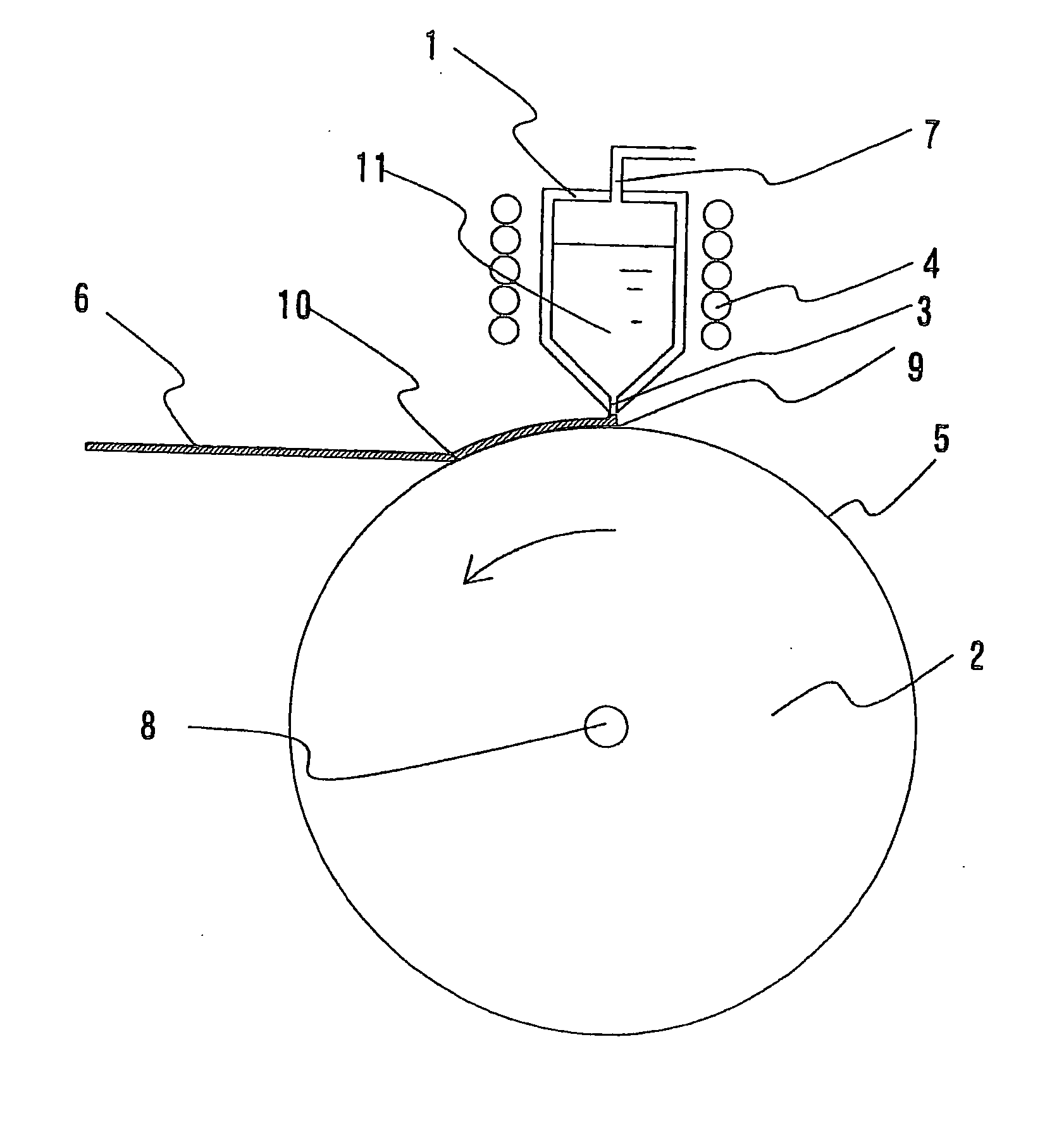
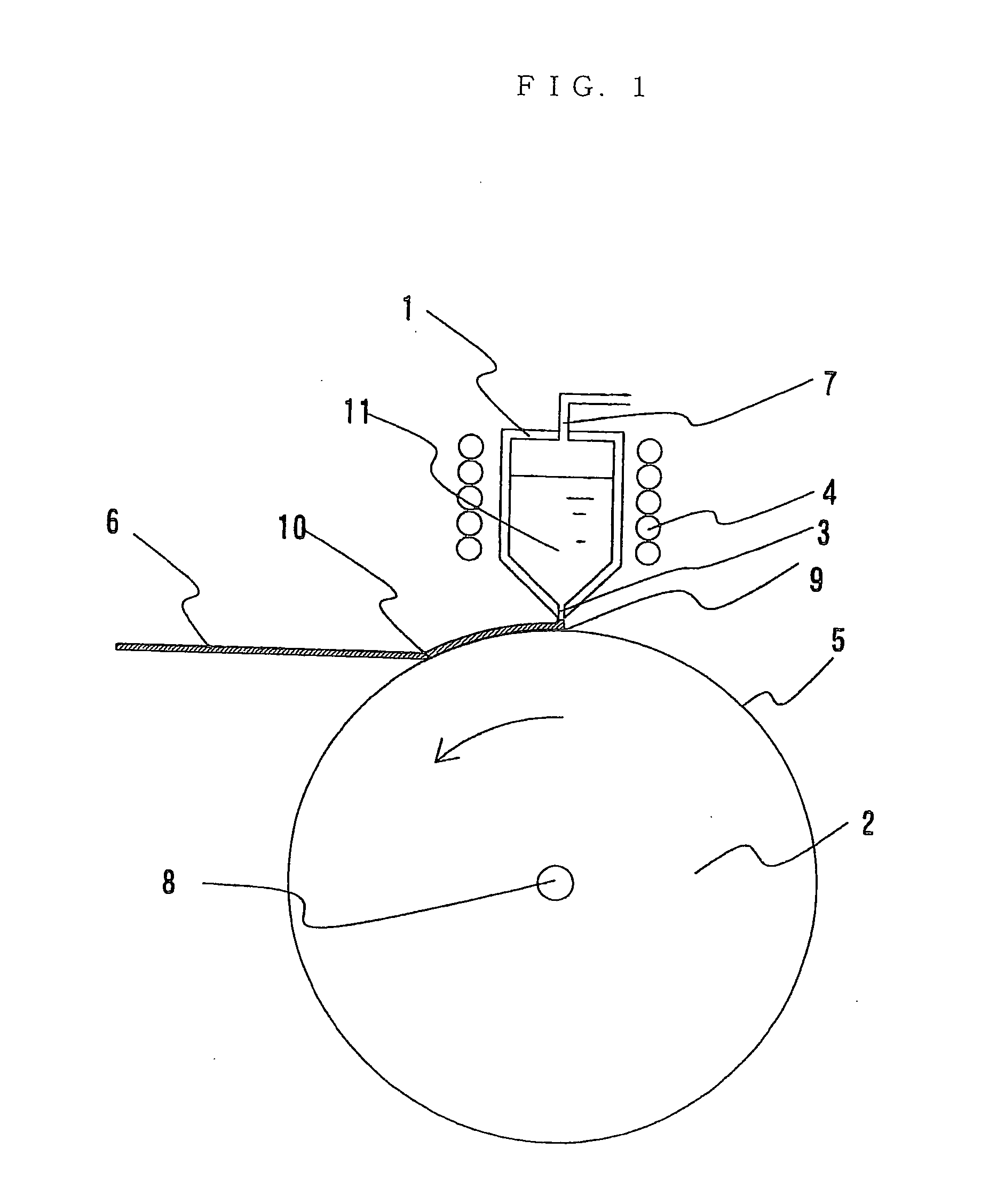
[0038] A foil of a niobium alloy was fabricated utilizing a single roll type alloy foil production unit having the structure illustrated in FIG. 1.

[0039] Crucible 1 was made of boron nitride based ceramics, and had a slit having a width of 0.4 mm and a length of 30 mm. Roll 2 was made of copper and had the dimensions: diameter of 300 mm and length of 80 mm. The distance between surface 5 of the roll and slit 3 was 0.5 mm. The roll was cooled with water. The number of rotations of the roll was set at 1500 rpm. A niobium alloy of 50 Nb-40 Ni-10 Zr (atomic %) was placed within the crucible. The inside of the crucible was heated to 1750° C., and the niobium alloy was completely melted. After that, an argon gas was injected into the crucible so that the melt was jetted from the slit so as to form a foil layer on the surface of the roll, and this foil layer was continuously peeled from the roll, so as to gain a niobium alloy foil (Example 1) having a thickness of 0.03 mm. The pressure wi...


PUM

PropertyMeasurementUnit
Percent by atomaaaaaaaaaa

Abstract

A hydrogen permeation membrane having excellent hydrogen permeability and hydrogen embrittlement resistance, and a production method thereof. This membrane is made of a niobium alloy foil having an amorphous crystal structure, the niobium alloy foil comprising 5 to 65 atomic % of at least one member selected from the group consisting of Ni, Co and Mo as a first additive element and 0.1 to 60 atomic % of at least one member selected from the group consisting of V, Ti, Zr, Ta and Hf as a second additive element together with the balance of Nb as an indispensable constituent element wherein 0.01 to 20 atomic % of Al and / or Cu may be contained as a third additive element. This alloy foil can be produced through a method comprising preparing a metal mixture of the above formulation, heating the metal mixture to the melting point or higher in an inert gas so as to melt the same and forming the melt into a film (foil) according to a liquid quenching technique.

Description

TECHNICAL FIELD [0001] The present invention relates to a metal foil (niobium alloy foil) which is useful as a hydrogen permeable membrane for a hydrogen refining unit that is utilized for fuel batteries and in semiconductor related fields, and to a production method of the metal foil. BACKGROUND ART [0002] In recent years, practical application of hydrogen refining units and fuel batteries that utilize the hydrogen refining units, as well as dissemination thereof have been desired, as a measure against global warming. Such hydrogen refining units have a first and second chamber, where the first chamber is isolated from the second chamber by a membrane. Thus, when a gas that includes hydrogen flows into the first chamber, the membrane functions so as to be substantially permeable to hydrogen in such a manner that a hydrogen enriched gas is collected in the second chamber while a gas that includes impurities (such as CO and CO2) remains in the first chamber. For this reason, so-calle...

Claims


Application Information

Patent Timeline
IPC IPC(8): B01D53/22B01D71/02B22D11/06B22D11/106C01B3/50
CPCB01D53/228B01D71/022B01D2257/108B01D2323/12B22D11/0611B22D11/106C01B3/503B01D71/0221B01D71/02232B01D69/06B01D67/0074B01D2256/16B01D2323/21811
Inventor INOUEKIMURA, HISAMICHIYAMAURA, SHINICHINISHIDA, MOTONORIOKOCHI, HITOSHISHINPO, YOICHIRO
Owner FUKUKA METAL FOIL & POWDER CO LTD
Learn More