
Iron-based mixed powder for powder metallurgy and sintered body

a technology of iron-based mixed powder and powder metallurgy, which is applied in the direction of metal-working apparatus, transportation and packaging, etc., can solve the problems of oxidization and deterioration of the quality of the material of the tool, and achieve the effect of improving machinability

Inactive Publication Date: 2006-03-30
JFE STEEL CORP
View PDF7 Cites 13 Cited by
  • Summary
  • Abstract
  • Description
  • Claims
  • Application Information

AI Technical Summary

Benefits of technology

[0012] The purpose of this invention is to solve the problem of the above-mentioned conventional technology advantageously. This invention aims at offering the iron-based mixed powder for powder metallurgy, which can improve machinability, without being accompanied by degrading the mechanical property of a sintered body.
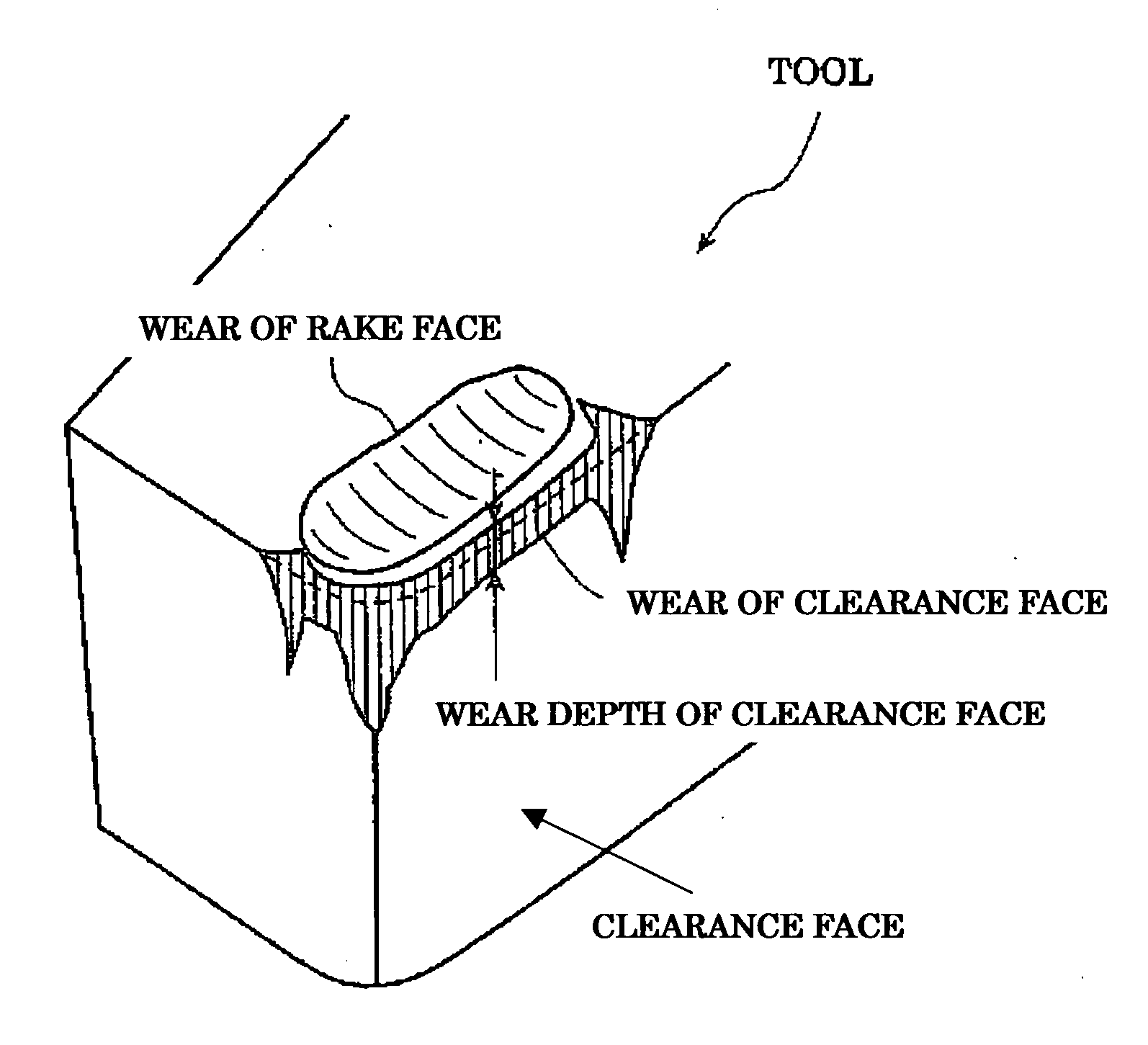
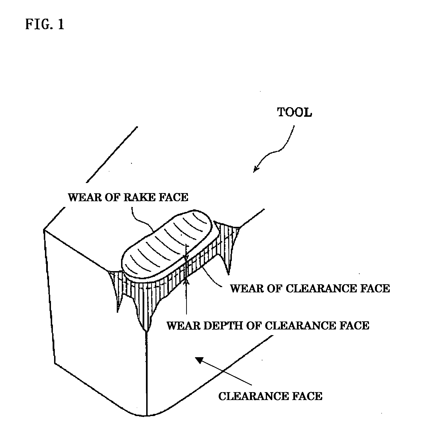
[0016] When, additional to MnS, calcium phosphate and / or the hydroxy apatite is co-added, and distributed in a sintered body, the particles of calcium phosphate and / or hydroxy apatite which are exposed to the working-side (cut area to be worked) at the time of cutting adhere on the surface of a tool, resulting in forming a tool protective film, while MnS promotes cutting-scraps to be a fine small-sized ones. Resultantly, above mechanisms prevent or suppress deterioration of the tool surface at the time of cutting, ending up in improving a tool life notably.

Problems solved by technology

However, the tool surface contacts a work material (the material to be cut) directly and generates heat by friction in the atmosphere, the quality of the material of a tool deteriorates by oxidization on the surface of a tool.
Therefore, such a chipping effect cannot obtain a sufficient result such as remarkable reduction of tool wear, leading to a remarkable improvement of machinability.

Method used


Image

  • Iron-based mixed powder for powder metallurgy and sintered body
  • Iron-based mixed powder for powder metallurgy and sintered body
  • Iron-based mixed powder for powder metallurgy and sintered body

Examples


first embodiment

Example 1

[0066] The following materials were prepared.

[0067] a) As an iron-based powder 100 kg, the atomized pure iron powder A (brand: JIP 301A™ (product made from JFE Steel Corp.)), the atomized pure iron powder B (brand: JIP 260A™ (product made from JFE Steel Corp.)) and,

[0068] b) As a powder for an alloy, graphite powder (average particle diameter: 4 micrometers) or electrolytic cupper powder (average particle diameter 35 micrometers),

[0069] c) As a powder for a machinability improvement, which has the kind, the particle diameter and the blending amount shown in Table 1.

[0070] The above-mentioned-materials a) b) c) were mixed with lubricant. Afterwards, they were charged into V shaped blender, and mixed homogeneously to be an iron-based mixed powder. The blending amount of the powder for an alloy and the powder for a machinability improvement were determined in mass %, based on the amount of the sum total of iron-based powder, the powder for an alloy, and the powder for a m...

example 2

[0081] The following materials were prepared.

[0082] a) As an iron-based powder, the atomized pure iron powderA (brand: JIP 301A™ (product made from JFE Steel Corp.)).

[0083] b) As a powder for an alloy, graphite powder (average particle diameter: 18 micrometers) or electrolytic cupper powder (average particle diameter: 35 micrometers).

[0084] c) As a powder for a machinability improvement, which has the kind, the particle diameter and the blending amount shown in Table 2.

[0085] d) A binder, whose kind and the blending amount are shown in Table 2.

[0086] The above-mentioned materials, a)-d) were blended to be mixed. Afterwards, they were charged into a heating-mixer. Here, the materials were cooled, after being heated and mixed at 140 degrees C. (This temperature means a point of higher by 15 degrees C. than the minimum melting point of a binder.) And then, the mixed materials came to be an iron-based powder, in which the powder for an alloy and the powder for a machinability impro...

second embodiment

[0094] The 2nd embodiment comprises an iron-based mixed powder, by mixing iron-based powder, the powder for an alloy, the powder for machinability improvement, and lubricant. The powder for machinability improvement comprises manganese sulfide powder and / or calcium fluoride powder, whose average particle diameter is 1 to 60 micrometers, and whose content is 0.1 to 1.5 mass % in total based on the amount of sum totals of iron-based powder, the powder for an alloy, and the powder for machinability improvement.

[0095] Moreover, in this embodiment, it is desirable that it is characterized that the particle size distribution of the powder, which consists of at least one sort of manganese sulfide powder and calcium fluoride powder, is substantially the same as the size distribution of pores of a sintered body, obtained by compacting the iron-based mixed powder without adding manganese sulfide powder or calcium fluoride powder and by sintering the formed iron-based mixed powder.

[0096] Fur...


PUM

PropertyMeasurementUnit
particle diameteraaaaaaaaaa

Abstract

The invention provides an iron-based mixed powder for powder metallurgy enabling the iron-based mixed powder to improve the machinability, without being accompanied by degrading the mechanical property of a sintered body. In order to obtain the purpose of the invention, the iron-based mixed powder comprises a mixture of an iron-based powder, a powder for an alloy, a powder for machinability improvement, while further adding lubricant. And, (1) the powder for machinability improvement comprises a manganese sulfide powder, and at least one selected from the group consisting of a calcium phosphate powder and a hydroxy apatite powder, or, (2) the powder for machinability improvement has an average particle diameter of 1 to 60 micrometers and is at least one selected from the group consisting of manganese sulfide powder and calcium fluoride powder.

Description

TECHNICAL FIELD [0001] This invention relates to the iron-based mixed powder for powder metallurgy, and relates to the iron-based mixed powder for powder metallurgy that enables especially the machinability improvement of a sintered body. BACKGROUND ART [0002] Recently, progress of powder metallurgy technology makes it possible to produce the complicated form in need of high dimensional accuracy into near-net-form. And the products that are manufactured by making use of the powder metallurgy technology becomes applicable to a variety of technological fields. [0003] The iron-based mixed powder for powder metallurgy is produced as follows. At first, iron-based mixed powder, which is produced by mixing a powder for an alloy and a lubricant with iron-based powder, is filled up in a die cavity. Here, the powder for an alloy is one such as copper powder or graphite powder. The lubricant is one such as zinc stearate or lithium stearate. Second, they are pressurized to be formed, and subseq...

Claims


Application Information

Patent Timeline
Patent Type & Authority Applications(United States)
IPC IPC(8): C22C1/05B22F1/10
CPCC22C33/0228B22F1/0059B22F1/10
Inventor OZAKI, YUKIKOSUGIHARA, HIROSHIUENOSONO, SATOSHI
Owner JFE STEEL CORP
Learn More