
Input stage circuit of three-level dc/dc converter

a technology of input stage circuit and dc/dc converter, which is applied in the direction of dc-dc conversion, power conversion system, instruments, etc., can solve the problems of unbalanced voltage applied to the mosfet, unbalanced voltage applied to the flying capacitor cb>3/b>, and inability to discharge through the freewheeling diod

Active Publication Date: 2006-03-09
DELTA ELECTRONICS INC
View PDF5 Cites 38 Cited by
  • Summary
  • Abstract
  • Description
  • Claims
  • Application Information

AI Technical Summary

Benefits of technology

[0020] Accordingly, the present invention is directed to an input stage circuit of a three-level DC / DC converter to solve the high voltage issue across the flying capacitor without affecting the operation of the circuit and increasing power consumption during discharging.
[0022] According to a preferred embodiment of the present invention, the input stage circuit of a three-level DC / DC converter uses the discharging module composed of metal-oxide-semiconductor field effect transistors (MOSFETs) to discharge the flying capacitor. Not only can the voltage across the flying capacitor be maintained at a desired value, but the circuit normally operates without power consumption. Accordingly, the high voltage issue across the prior art flying capacitor can be solved, while avoiding other problems in the prior art technology.

Problems solved by technology

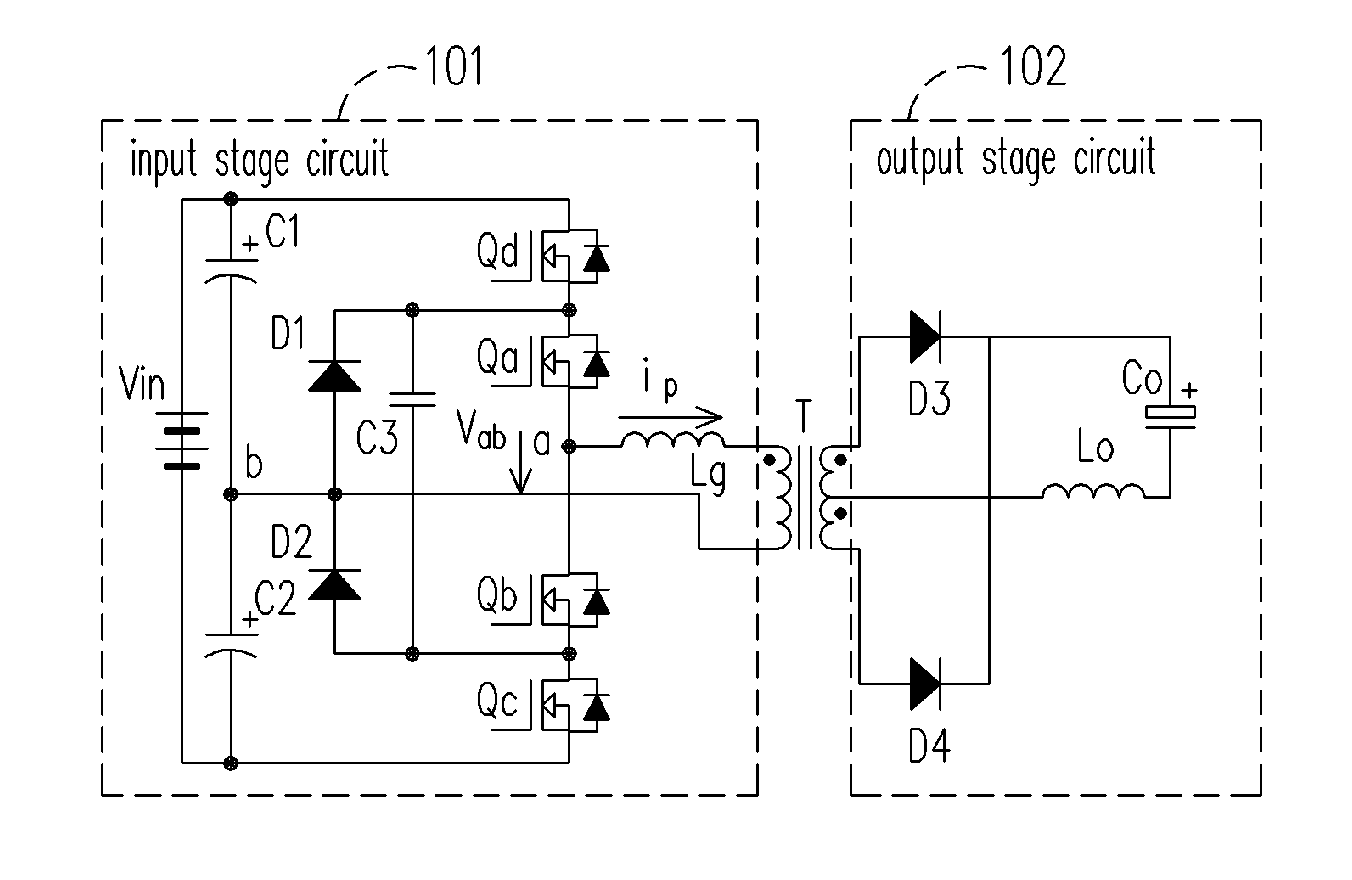
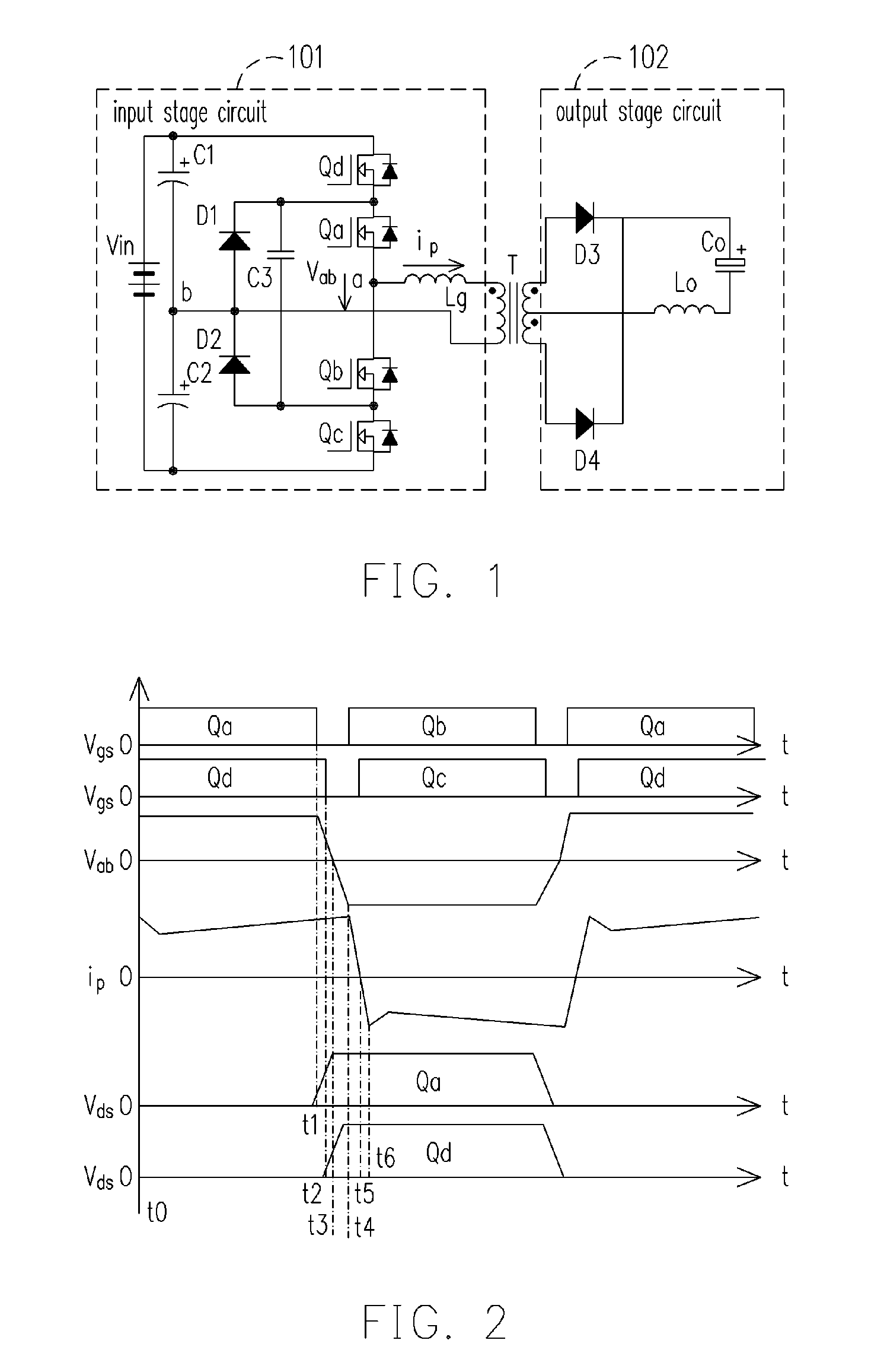
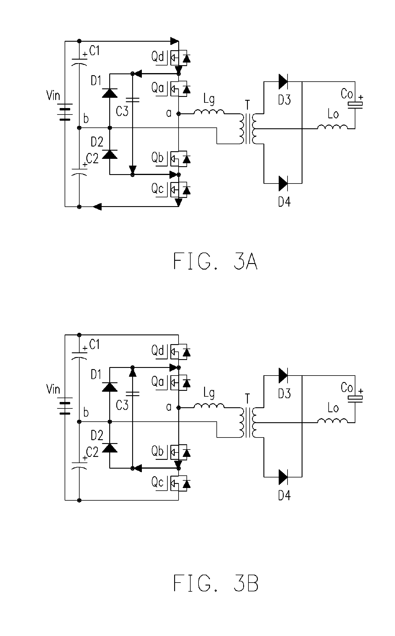
Moreover, the flying capacitor C3 cannot be discharged through the freewheeling diode D1 to the power source.
Accordingly, the voltage across the flying capacitor C3 is undesirably high.
Due to the high voltage across the flying capacitor C3, voltage applied to these MOSFETs becomes unbalanced.
Sometimes these MOSFETs would break down and damage the circuits.
The resistor, however, consumes power, and the value of resistance is hard to be determined.
If the resistance is too small or too large, the resistor will adversely affect or even disrupt the operation of the circuit.
This will undermine the operation of the circuit, and the TVS will completely consume the energy of the discharging.

Method used


Image

  • Input stage circuit of three-level dc/dc converter
  • Input stage circuit of three-level dc/dc converter
  • Input stage circuit of three-level dc/dc converter

Examples


Embodiment Construction

[0032] The following is a description of an input stage circuit of a three-level DC / DC converter according to an embodiment of the present invention.

[0033]FIG. 4 is a schematic configuration showing a three-level DC / DC converter according to an embodiment of the present invention. Wherein, the left side of the transformer T is the primary side, which is coupled to the input stage circuit 401 of the present embodiment. The right side of the transformer T is the secondary side, which is coupled to the output stage circuit 102 as shown in FIG. 1.

[0034] The input stage circuit 401 comprises several devices. The positive input terminal I1 and the negative input terminal 12 are coupled to the input voltage Vin. The switch module 402 is coupled between the positive input terminal I1 and the first terminal E1 of the primary side. The switch module 403 is coupled between the negative input terminal I2 and the first terminal E1 of the primary side. Both switch modules control the connection...


PUM


Abstract

An input stage circuit of a three-level DC / DC converter is provided. The input stage circuit uses metal-oxide-semiconductor field effect transistors (MOSFETs) to discharge a flying capacitor to maintain the voltage across the flying capacitor at a half of the input voltage. Not only can the input stage circuit solve the high voltage issue across the flying capacitor in the prior art, but the circuit is able to operate normally without increasing power consumption during discharging, thereby avoiding problems of the prior art.

Description

CROSS-REFERENCE TO RELATED APPLICATION [0001] This application claims the priority benefit of Taiwan application serial no. 93127238, filed on Sep. 9, 2004. All disclosure of the Taiwan application is incorporated herein by reference. BACKGROUND OF THE INVENTION [0002] 1. Field of the Invention [0003] The present invention relates to a DC / DC converter, and more particularly, to an input stage circuit of a three-level DC / DC converter. [0004] 2. Description of the Related Art [0005] Three-level DC / DC converters with zero-voltage-switching (ZVS) have been adapted for various high-voltage and high-power applications, such as telecommunication systems, battery chargers, and uninterruptible power supply systems. The advantage is low power consumption and high efficiency. [0006]FIG. 1 is a schematic drawing showing a conventional three-level DC / DC converter. The three-level DC / DC converter comprises an input stage circuit 101, a transformer T, and an output stage circuit 102. Wherein the i...

Claims


Application Information

Patent Timeline
IPC IPC(8): H02M3/335H02M7/487H02M7/538
CPCH02M7/487H02M3/33569H02M3/33571
Inventor ZENG, JIANHONGYING, JIANPINGDENG, XIAOJUNGUO, XINGKUANXIONG, AIMING
Owner DELTA ELECTRONICS INC
Learn More