Eureka AIR delivers breakthrough ideas for toughest innovation challenges, trusted by R&D personnel around the world.

Socket

a technology of sockets and light-emitting diodes, which is applied in the field of sockets, can solve the problems that the light-emitting diodes for auxiliary light and other light-emitting elements inside the final product cannot be detected intermittently by the camera module, and the shell-shaped light-emitting diodes have not been used in portable telephones, etc., to achieve stable electrical connection, improve autofocusing precision, and auxiliary light

Inactive Publication Date: 2005-12-15
AVAGO TECH INT SALES PTE LTD
View PDF7 Cites 22 Cited by
  • Summary
  • Abstract
  • Description
  • Claims
  • Application Information

AI Technical Summary

Benefits of technology

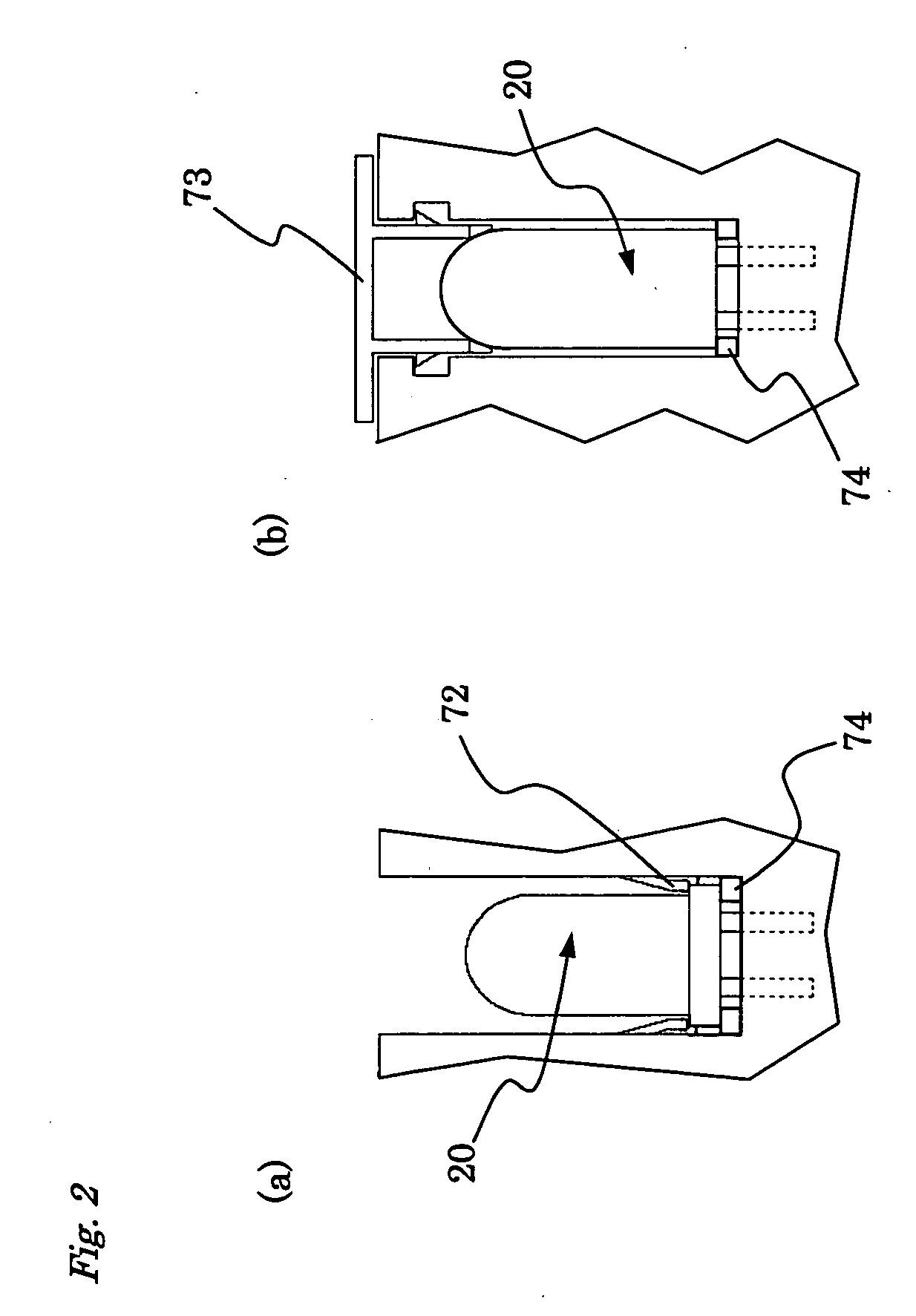
[0012] The anchor for setting the dome direction of the light-emitting diode engages with the curved surface of the dome section of the light-emitting diode, or a flange part or pedestal part disposed near the base end of the dome section, and sets the direction of the dome section. The anchor further acts such that an unintentional detachment of the light-emitting diode from the socket is prevented.
[0013] Furthermore, the socket of the present invention has the appropriate light-blocking means for preventing emitted light from the light-emitting diode from reaching the camera module. The light-blocking means is part of the housing or part of an electromagnetic shield for preventing interference with signals provided to the camera module. The electromagnetic shield can extend to the case housing of the final product or can be placed near the inside surface of the housing and when necessary, can be grounded.
[0014] The socket housing can also comprise additional circuit wiring between the camera module and the light-emitting diode, and this wiring can be held inside the housing together with an IC. For instance, switching components that are capable of controlling the light-emitting diode in accordance with the output of the camera module can be kept inside the housing. Furthermore, the socket housing can be such that it will hold additional light-receiving elements. For instance, autofocusing precision can be improved by a combined processing of detected signal data obtained from elements capable of detecting color with data detected from the camera elements or operating data from the light-emitting diode.
[0015] The present invention provides a structure for stable electrical connection to a light-emitting diode for auxiliary light that is simple and facilitates assembly. The direction of the optical axis of the dome section of the light-emitting diode is brought to face a predetermined relative position with respect to the optical axis of the camera module and is securely maintained in a state such that this optical axis will not shift. The socket, including the structure for holding the light-emitting diode for auxiliary light, can be connected to the flexible circuit board by reflow soldering during production; therefore, the camera module and light-emitting diode can thereafter be efficiently attached simultaneously.

Problems solved by technology

A light-emitting diode with a high light intensity is preferred as the auxiliary light for autofocusing, but a shell-shaped light-emitting diode with a relatively high light intensity has not been used in portable telephones because it cannot be soldered to the flexible circuit board.
In addition, whether the light-emitting diode is shell-shaped or surface-mounted, light from the light-emitting diode for auxiliary light and other light-emitting elements inside the final product should not be detected intermittently by the camera module.

Method used


Image

  • Socket
  • Socket
  • Socket

Examples


first embodiment

[0028] By means of the first embodiment, housing 40 has a wall part 41 that extends higher than housing 90 that holds camera module 30, and an electromagnetic shield 80 disposed such that current applied to light-emitting diode 20 will not affect the camera module or other peripheral elements. Wall part 41 and electromagnetic shield 80 extend up to near the outside case housing CH of the device that holds the flexible circuit board assembly, including socket 10; therefore, light emitted from light-emitting diode 20 is blocked by the concerted action of both the wall part 41 and the electromagnetic shield 80 or the singular action of one of these, and any irradiation to camera module 30 by this emitted light is prevented.

[0029] Furthermore, the part of electromagnetic shield 80 that extends between light-emitting diode 20 and camera module 30 is shown by a broken line near flexible circuit board CB in order to emphasize the linked structure of housings 40 and 90. For instance, it is ...

second embodiment

[0039] This embodiment is similar to the second embodiment, but it is different in that a housing 340 does not have a relatively high light-blocking wall and only an electromagnetic shielding member 380 extends up near the inside surface of case housing CH. The present embodiment has advantages in that it provides the appropriate light-blocking means for a light-emitting diode 320 and a camera module 330 and it facilitates molding during the production of housing 340, as well as the attachment and assembly of light-emitting diode 320 and camera module 330.

[0040] By means of the above-mentioned first through fourth embodiments, light-emitting diodes 20, 120, 220, and 320 are aligned in the direction of height by bringing flange parts 24, 124, 224, and 324 into contact with step parts 46, 146, 246, and 346 formed in housings 40, 140, 240, and 340. However, as shown in FIG. 6, it is also possible to bring a flange part 28 formed in a lead 21 into contact with a shoulder part 49 formed ...


PUM


Abstract

A socket in which a light-emitting diode can be attached and detached as needed close to the structure for holding a camera module. Socket comprises a spring contact part for contacting the leads or electrodes of the light-emitting diode, and an anchor for anchoring such that the direction of a dome section has a predetermined relationship with the camera module.

Description

FIELD OF THE INVENTION [0001] The present invention pertains to a method for loading a light-emitting diode, and is used together with a camera module in portable telephones and similar equipment. DISCUSSION OF THE BACKGROUND ART [0002] There are portable telephones and similar equipment being marketed wherein a camera module with an autofocus function is housed in the portable terminal, but the use of auxiliary light for autofocusing such as is used by digital cameras is also being considered for these telephones. [0003] Camera units that use the auxiliary light employed in digital cameras are cited, for instance, in JP (Kokai) 2003-114,369 and JP (Kokai) 2003-319,405. The general structure of the camera unit is shown in the latter reference. The unit comprises a camera module and a light-emitting diode as the auxiliary light source; the diode is disposed facing in the same direction as and in juxtaposition with the camera module. [0004] A light-emitting diode used as an auxiliary ...

Claims


Application Information

Patent Timeline
Patent Type & Authority Applications(United States)
IPC IPC(8): G02B7/28G03B13/36G03B17/02H01L33/00H01R33/05H01R33/06H04N5/222H04N5/225H04N5/232
CPCH04N5/2256H04N23/56
Inventor TAKEKUMA, AKIRAYAMAOKA, YOSHIFUMI
Owner AVAGO TECH INT SALES PTE LTD
Why Eureka
Eureka Blog
Learn More