
Method for calculating a transmission window size

a transmission window and transmission window technology, applied in the field of transmission window size calculation, can solve the problems of network congestion, large window risk, network congestion,

Inactive Publication Date: 2005-11-17
TELEFON AB LM ERICSSON (PUBL)
View PDF10 Cites 35 Cited by
  • Summary
  • Abstract
  • Description
  • Claims
  • Application Information

AI Technical Summary

Benefits of technology

[0018] The invented method can comprise the additional steps of storing the selected window size together with an indication of the pipe capacity, or a predefined range of pipe capacities comprising the pipe capacity, of the connection. The storing of the selected window size has the advantage that a selected window size can be used for further connections. The storing of the pipe capacity or a predefined range of pipe capacities comprising the pipe capacity, of the connection has the advantage that a stored window size can be selected depending on the pipe capacity.

Problems solved by technology

However, a fixed larger initial window bears the risk that the window is too large in some situations, where congestion occurs somewhere in the network.
In such situations a too large window contributes on top to the congestion, which could lead potentially to problems.
Increasing a TCP sender's IW, LW, and RW can significantly improve end-to-end performance but also bears the risk of causing network congestion.
Nevertheless, if congestion can also occur within that “private” network, it is problematic to find optimal values for IW, LW, and RW.
However, this mechanism is limited to the use in the case that the sender and receiver of the new connection are the same as of an ongoing connection.
Currently there is no mechanism that enables to adapt the window size for a packet switched connection in a way that avoids the waste of transmission resources.
An increase of window sizes above the upper threshold value would lead to packet losses and by that to less efficient use of transmission capacities.
The maximum bit rate on an air interface varies strongly while transmission capacity on the air interface is expensive.

Method used


Image

  • Method for calculating a transmission window size
  • Method for calculating a transmission window size
  • Method for calculating a transmission window size

Examples


Embodiment Construction

[0044] In the following the invention will be described by means of figures and embodiments. The invention will be explained by using a network comprising a mobile network without restricting the invention to such implementation.

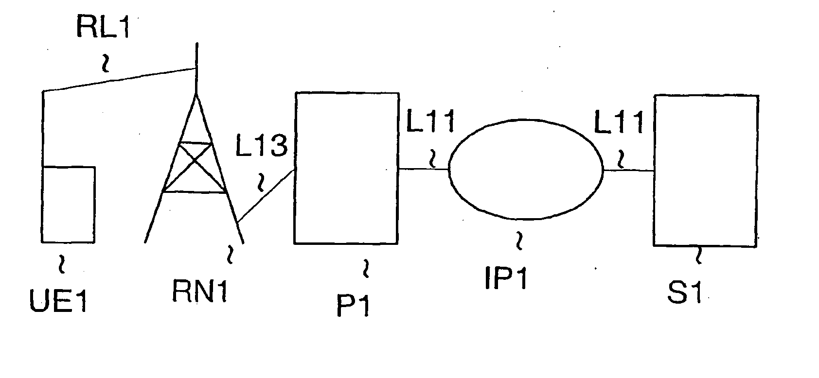
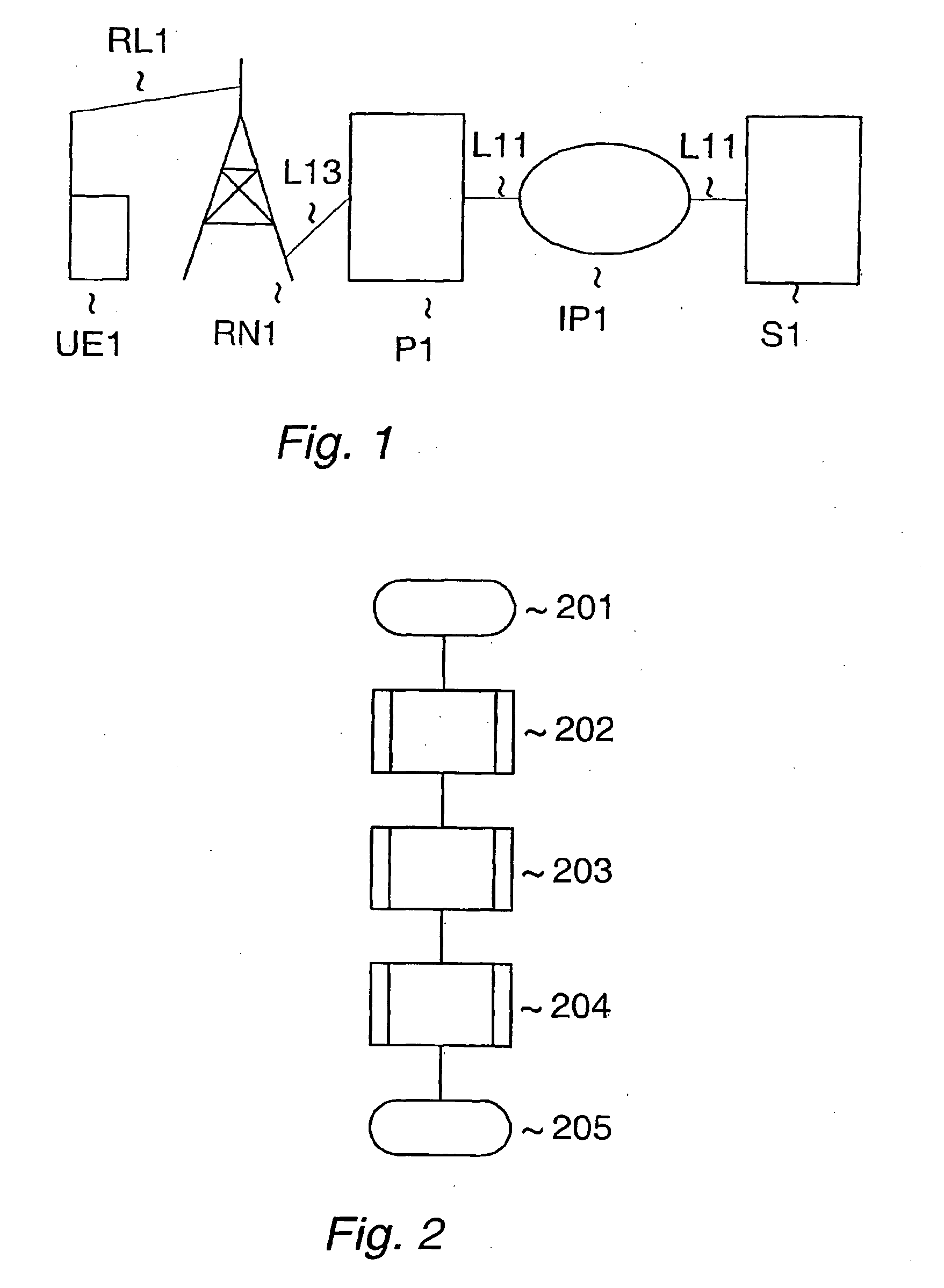
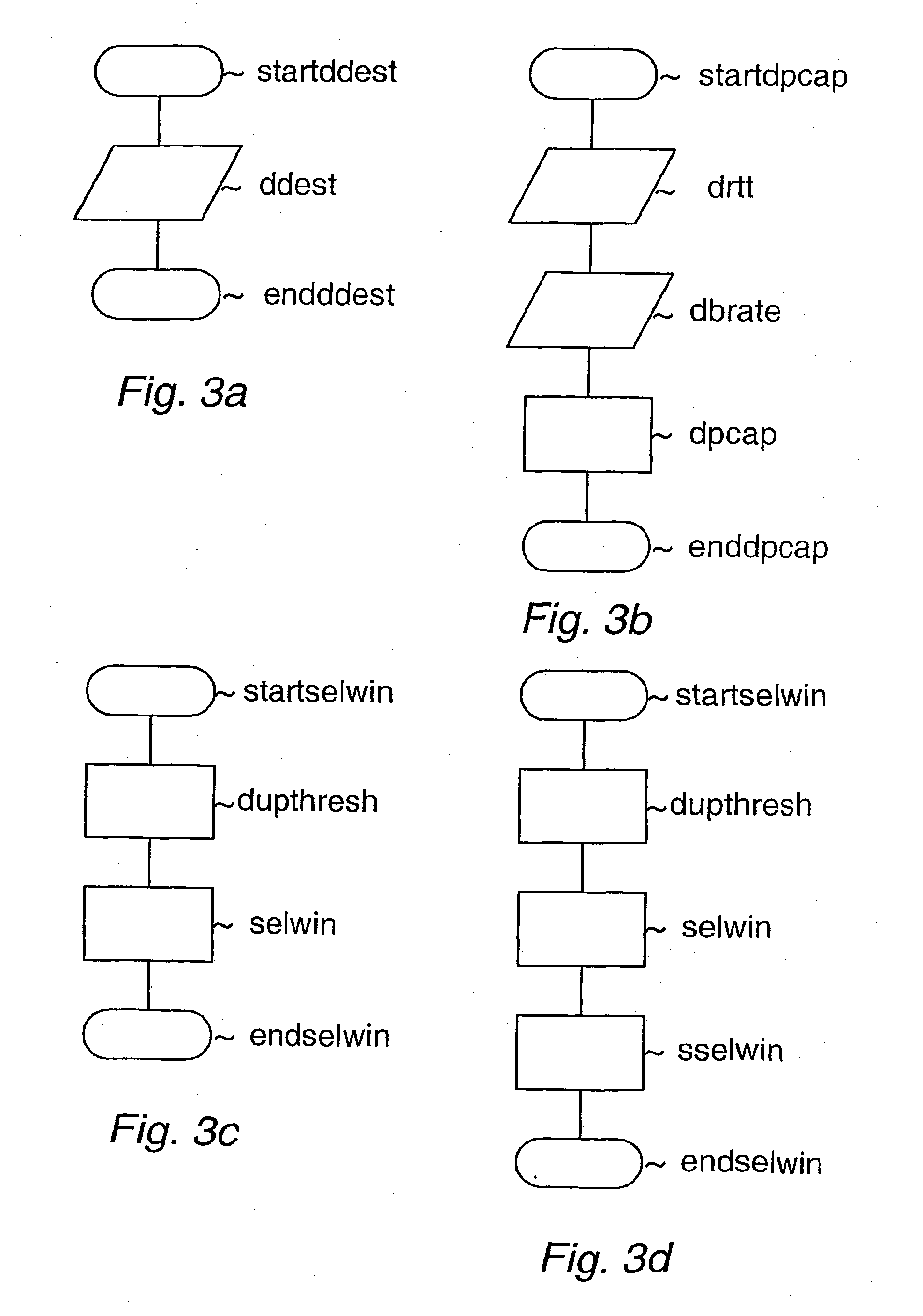
[0045]FIG. 1 depicts a schematic of a communication path between a first party UE1 and a server S1. The server is connected via a link L11 to an IP based network IP1. Said IP based network is connected via a link L12 to a proxy server P1. Said proxy server is used to connect the fixed connected domain comprising the before mentioned components with a wireless domain via a link L13. The wireless domain comprises the network for mobile telecommunications RN1 and the first party ULE1. The network for mobile telecommunications RN1 is connected to the proxy via said link L13. It is further connected to the first party UE1 via a radio link RL1. The proxy P1 acts as a party towards the server S1 and the first party UE1. In the following the connection radio link R...


PUM


Abstract

The invention relates to a method for selecting a window size for a packet switched connection between a first and a second party. The associated window is used by a sending party for a window based congestion control mechanism for avoiding or handling congestion on a communication path. The invented method enables to adapt the size of an initial window, a loss window, and a restart window based on information available in the network to increase the utilisation of transmission capacity.

Description

TECHNICAL FIELD OF THE INVENTION [0001] The invention relates to a method for selecting a window size for a packet switched connection between a first and a second party. The associated window is used by a sending party for a window based congestion control mechanism for avoiding or handling congestion on a communication path. The window size defines the maximum number of data packets that can be sent by a sending party before an acknowledgement of the reception of a packet is received by said sending party. DESCRIPTION OF RELATED ART [0002] Communication systems using window based congestion control are well known as for example systems operating according to a TCP / IP (Transmission Control Protocol / Internet Protocol) or systems operating according to a SCTP (Stream Control Transmission Protocol). Such systems permit the sending of a certain number of packets from a sender to a receiver, before an acknowledgement of a reception of a packet is received at the sender. The number of pa...

Claims


Application Information

Patent Timeline
Patent Type & Authority Applications(United States)
IPC IPC(8): H04L47/27
CPCH04L29/06H04L47/10H04L47/11H04L47/14H04L47/18H04L47/193H04L69/163H04L47/27H04L47/283H04L47/29H04L69/16H04L67/04H04L47/263H04W28/10H04L47/36H04L9/40H04W8/04
Inventor WAGER, STEFANLUDWIG, REINERMEYER, MICHAELJONSSON, ANDERSEKSTROM, HANNES
Owner TELEFON AB LM ERICSSON (PUBL)
Learn More