Method and circuit for improving device power up timing and predictability

Inactive Publication Date: 2005-09-29
CETIN JOSEPH +1
View PDF21 Cites 14 Cited by
  • Summary
  • Abstract
  • Description
  • Claims
  • Application Information

AI Technical Summary

Benefits of technology

[0010] In another example, the method may also include boosting the first supply voltage to provide for faster power-up of the first supply voltage and the first subsystem. The method may also include boosting-the second supply voltage to provide for faster power-up of the second supply voltage and the second subsystem. Signals within or between subsystems that are bias signals or voltages may also be boosted or pre-biased for faster startup, so that these bias signals are providing their desired bias levels in a rapid time, which helps to improve the startup time of the subsystem containing the boosted bias signal.
[0013] In another example, the integrated circuit may include a boost circuit for boosting the first supply voltage, and a boost circuit for boosting the second supply voltage. Signals within or between subsystems that are bias signals or voltages may also be boosted or pre-biased for faster startup, so that these bias. signals are providing their desired bias levels in a rapid time, which helps to improve the startup time of the subsystem containing the boosted bias signal.
[0017] According to another embodiment, a method is disclosed for providing predictable power-up sequences for a device or system, in accordance with an embodiment of the present invention, which can be used for starting up circuits that otherwise do not have deterministic relationships of clock and data, thereby to avoid metastability. The method can also be used to more rapidly bring a device out of power-down (sleep) state.

Problems solved by technology

Typically, an output of a voltage regulator is applied to the entire device or system, which can cause some drawbacks.
A first drawback is that power up speed of the device or system may be limited by the performance / specifications of the voltage regulator.
A second drawback is that the device or system which uses the voltage regulator may have many sub-blocks, and once the regulator is activated, the sub-blocks may come up out of a power down state in a non-predictable or non-deterministic sequence.
For example and as recognized by the present inventors, in a phase lock loop (PLL), it may be desirable to have the reference clock to be active before the PLL is active, but the unpredictability of conventional power up schemes such as of FIG. 1 may inhibit this.

Method used


Image

  • Method and circuit for improving device power up timing and predictability
  • Method and circuit for improving device power up timing and predictability
  • Method and circuit for improving device power up timing and predictability

Examples


Embodiment Construction

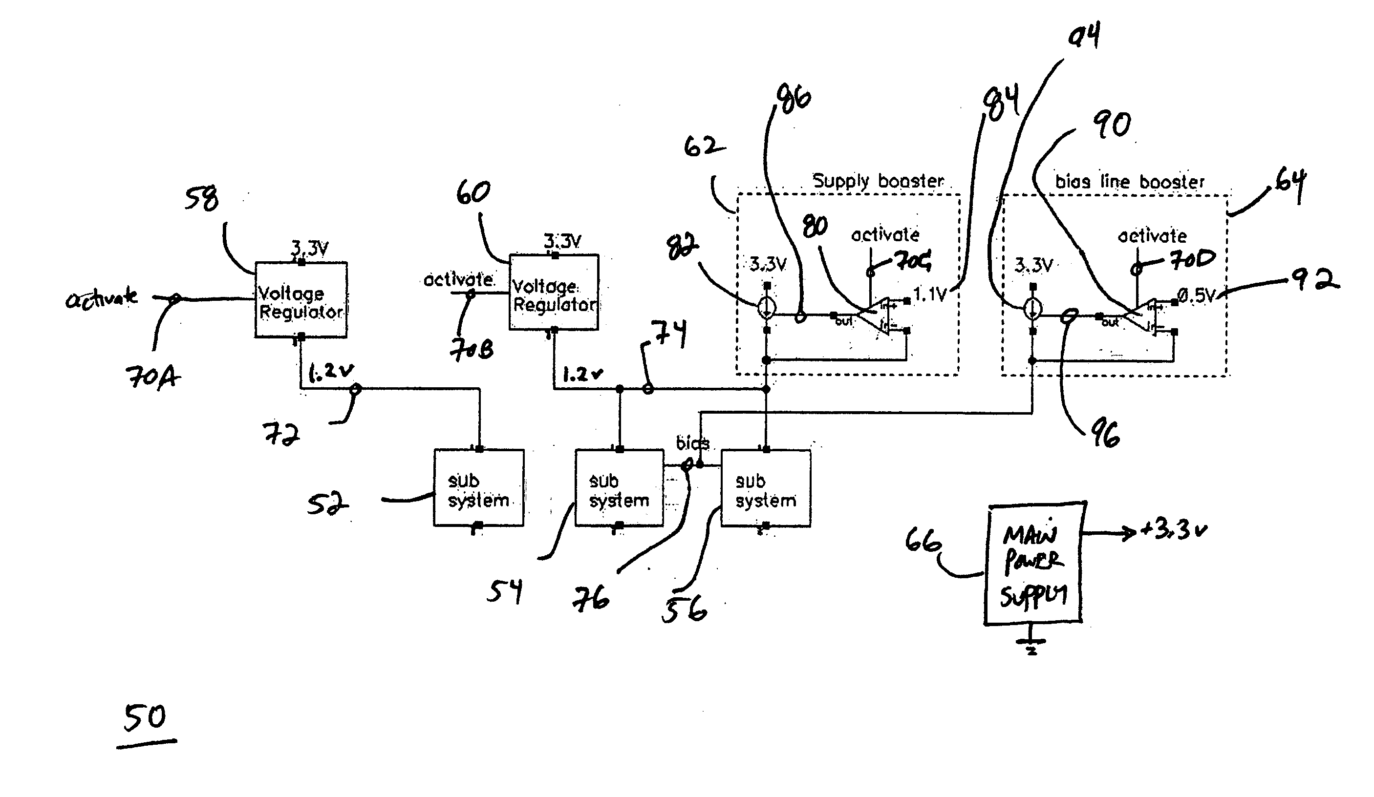
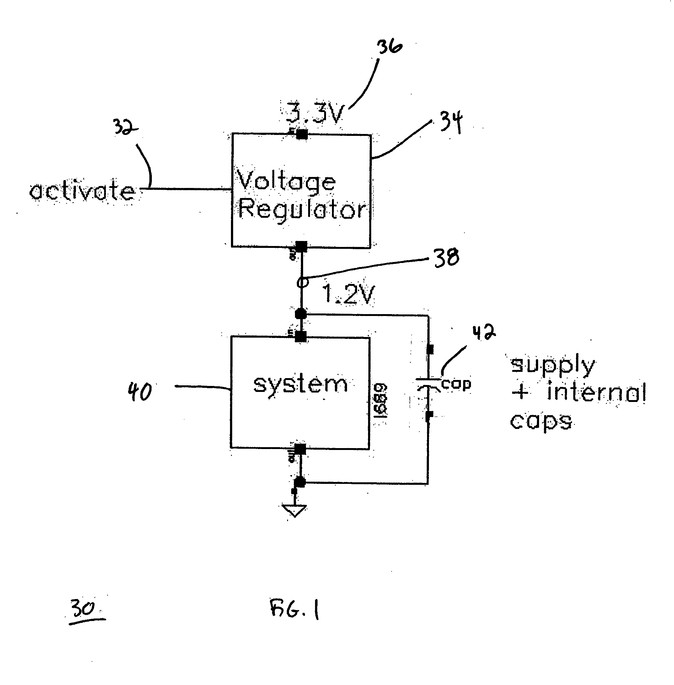
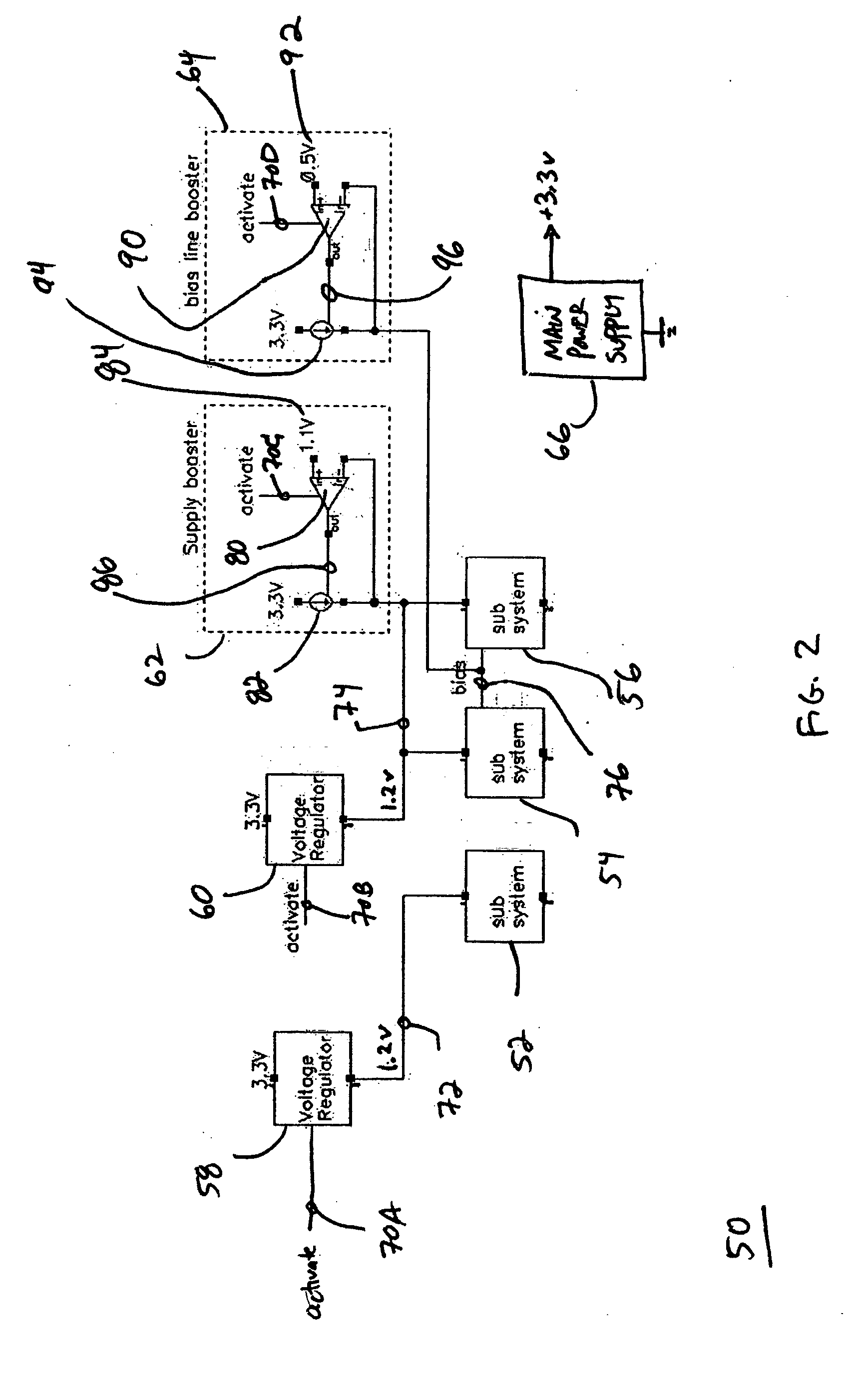
[0023] Embodiments of the present invention provide predictable startup sequencing and priority control of one or more sections, blocks, circuits, components or subsystems (referred to herein interchangeably as “subsystems”) either within an integrated circuit or device, or distributed amongst discrete circuit components of an electronic system. Embodiments of the invention may also provide improved or faster start-up timing of circuits or subsystems, if desired. For instance, boost circuits can be used to boost supply lines or bias lines, and these boost circuits can also be used to indicate when a subsystem has a stable supply or bias signal. Various embodiments of the present invention will now be described.

[0024] In one example, one or more voltage controllable regulators are provided and associated with one or more subsystems of a device or system. A controllable voltage regulator may be provided to supply a regulated voltage supply signal to a particular subsystem of an overa...


PUM


Abstract

Method and system for controllably and sequentially powering up subsystems of an electronic system, device or integrated circuit. In one example, a first supply voltage is selectively applied to a first subsystem, and when the first supply voltage has reached a predetermined value, a second supply voltage is selectively applied to the second subsystem. The first and second supply voltages may also be boosted to provide fast startup timing. In this manner, the first subsystem is powered-up before the second supply voltage is applied to the second subsystem—this provides for controlled, sequential power up of the subsystems of the electronic system, device or integrated circuit.

Description

CROSS REFERENCE TO RELATED APPLICATION [0001] This application claims priority under 35 U.S.C. 119(e) to U.S. provisional patent application Ser. No. 60 / 556,968 filed Mar. 26, 2004 and entitled “Method of Improving Device Power Up Timing and Predictability,” the disclosure of which is hereby incorporated by reference in its entirety.FIELD OF THE INVENTION [0002] This invention relates, in general, to electronic circuits, and in particular to circuits for controlling power in an integrated circuit or electronic system. BACKGROUND OF THE INVENTION [0003] Many devices or systems, particularly those using low voltages and consuming low power, require a voltage regulator, either internal or external, that provides a regulated supply voltage. Low voltage regulators are frequently used in low voltage or low power devices. Typically, an output of a voltage regulator is applied to the entire device or system, which can cause some drawbacks. A first drawback is that power up speed of the devi...

Claims


Application Information

Patent Timeline
IPC IPC(8): G05F1/56H02H7/00
CPCG05F1/56
Inventor CETIN, JOSEPHMOYAL, NATHAN
Owner CETIN JOSEPH
Why Eureka
Try Eureka