
Piezoelectric ceramic and piezoelectric device

Inactive Publication Date: 2005-09-29
TDK CORPARATION
View PDF3 Cites 4 Cited by
  • Summary
  • Abstract
  • Description
  • Claims
  • Application Information

AI Technical Summary

Benefits of technology

[0011] In view of the foregoing, it is a first object of the invention to provide a piezoelectric ceramic and a piezoelectric device capable of being fired at a low temperature and improving piezoelectric properties.

Problems solved by technology

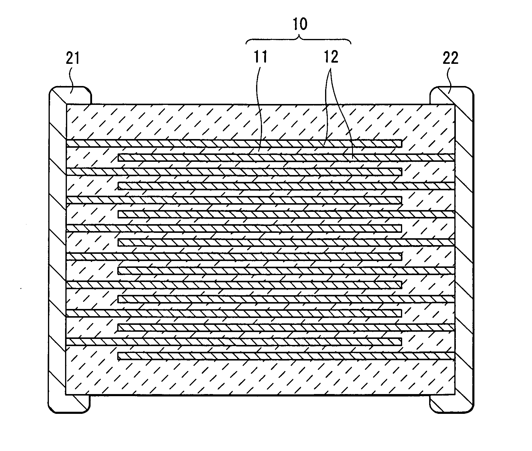
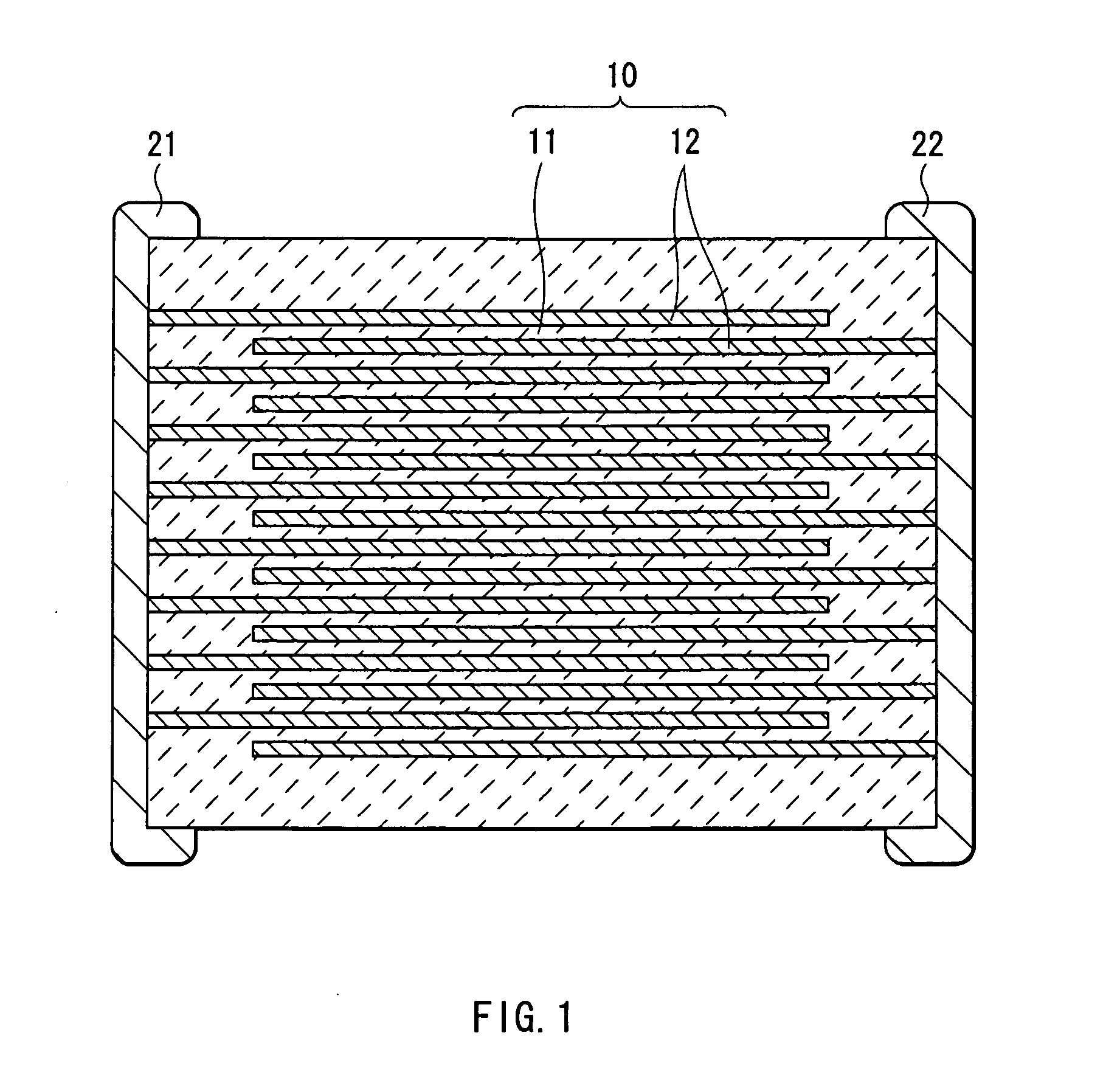
However, in a conventional piezoelectric ceramic, the firing temperature is as high as approximtely 1200° C., so when a multilayer piezoelectric device is manufactured, it is necessary to use an expensive noble metal such as platinum (Pt) or palladium (Pd) for the internal electrode, which causes a high manufacturing cost.
In addition, copper is a base metal, so copper is oxidized when copper is fired in an air atmosphere, thereby copper cannot be used as the electrode.
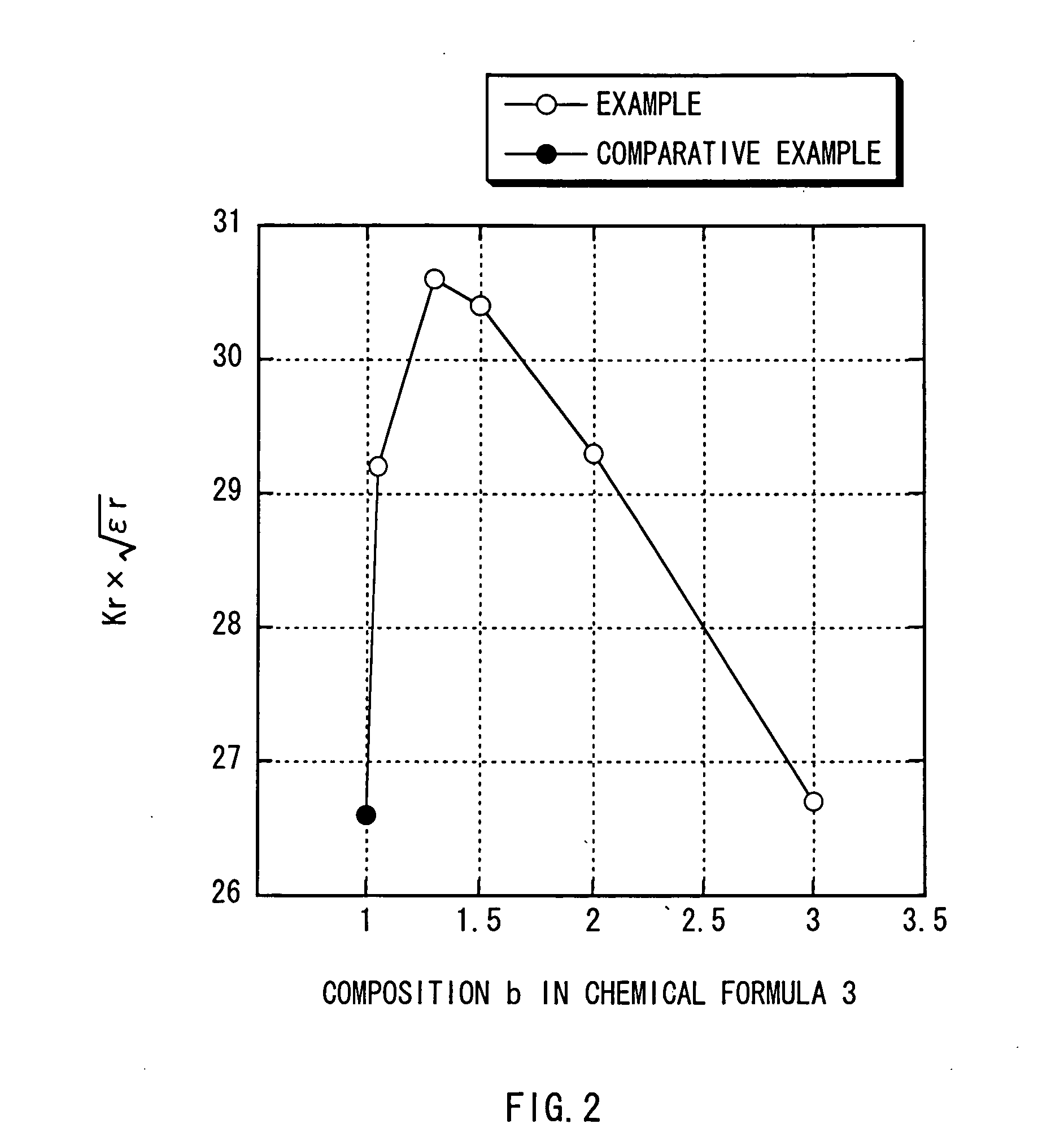
However, when the relative dielectric constant εr increases, the impedance declines, so when the piezoelectric device is driven, a large amount of current flows through the piezoelectric device, thereby an energy required for driving the piezoelectric device is increased.

Method used


Image

  • Piezoelectric ceramic and piezoelectric device
  • Piezoelectric ceramic and piezoelectric device
  • Piezoelectric ceramic and piezoelectric device

Examples


first embodiment

[0036] A piezoelectric ceramic according to a first embodiment of the invention includes a composition represented by Chemical Formula 1 as a main component. Such a composition including lead titanate, lead zirconate and lead zinc niobate can obtain high piezoelectric properties, and a high Curie temperature of 300° C. or more.

Pba[(Znb / 3Nb2 / 3)xTiyZrz]O3  (Chemical Formula 1)

[0037] In Chemical Formula 1, the values of a, b, x, y and z are within a range satisfying 0.94≦a≦1.02, 1<b≦3, x+y+z=1, 0.05≦x<0.125, 0.275<y≦0.5 and 0.375<z≦0.6, respectively. The composition of oxygen is stoichiometrically determined, and may deviate from the stoichiometric composition.

[0038] The composition represented by Chemical Formula 1 has a perovskite structure, and lead is positioned at the so-called A-site of the perovskite structure, and zinc, niobium, titanium (Ti) and zirconium (Zr) are positioned at the so-called B-site of the perovskite structure.

[0039] The composition a of lead in Chemical Fo...

second embodiment

[0058] A piezoelectric ceramic according to a second embodiment of the invention includes a composition represented by Chemical Formula 2 as a main component.

(Pbe·fMef)[(Zng / 3Nb2 / 3)uTivZrw]O3  (Chemical Formula 2)

[0059] In Chemical Formula 2, the values of e, f, g, u, v and w are within a range satisfying 0.96≦e≦1.03, 0.01≦f≦0.10, 1<g≦3, u+v+w=1, 0.05≦u<0.125, 0.275<v≦0.5 and 0.375<w≦0.6, respectively, and Me indicates at least one kind selected from the group consisting of strontium, barium and calcium. The composition of oxygen is stoichiometrically determined, and may deviate from the stoichiometric composition.

[0060] The composition represented by Chemical Formula 2 has a perovskite structure, and lead, strontium, barium and calcium are positioned at the so-called A-site of the perovskite structure, and zinc, niobium, titanium and zirconium are positioned at the so-called B-site of the perovskite structure. In the composition, at least one kind selected from the group consist...

examples

[0074] Next, specific examples of the invention will be described below.


PUM

PropertyMeasurementUnit
Percent by massaaaaaaaaaa
Temperatureaaaaaaaaaa

Abstract

A piezoelectric ceramic and a piezoelectric device capable of being fired at a low temperature and improving piezoelectric properties are provided. The piezoelectric ceramic and the piezoelectric device includes Pba[(Znb / 3Nb2 / 3)xTiyZrz]O3 (where 0.94≦a≦1.02, 1<b≦3, x+y+z=1, 0.05≦x<0.125, 0.275<y≦0.5, 0.375<z≦0.6) or (Pbe·fMef)[(Zng / 3Nb2 / 3)uTivZrw]O3 (where 0.96≦e≦1.03, 0.01≦f≦0.1, 1<g≦3, u+v+w=1, 0.05≦u<0.125, 0.275<v≦0.5, 0.375<w≦0.6, and Me indicates Sr, Ba or Ca). When an excessive amount of Zn is included, the firing temperature can be lower, and the piezoelectric properties can be improved.

Description

BACKGROUND OF THE INVENTION [0001] 1. Field of the Invention [0002] The present invention relates to a piezoelectric ceramic and a piezoelectric device applicable to, for example, a piezoelectric vibrator such as an actuator, a piezoelectric buzzer, a sound component and a sensor, and specifically suitable for a multilayer piezoelectric vibrator. [0003] 2. Description of the Related Art [0004] One of conventional devices using displacement generated by a piezoelectric effect as a mechanical driving source is an actuator. Specifically, compared to an electromagnetic actuator, a multilayer actuator in which a piezoelectric layer and an internal electrode are laminated has lower power consumption, a lower heating value and better responsivity, and the size and the weight of the multilayer actuator can be reduced. Therefore, in recent years, the multilayer actuator is used in various fields such as a needle selection control of a fabric-knitting machine. [0005] Piezoelectric ceramics us...

Claims


Application Information

Patent Timeline
IPC IPC(8): C04B35/491H01L41/083H01L41/187
CPCC04B35/493H01L41/1876C04B2235/3213C04B2235/3215C04B2235/3232C04B2235/3241C04B2235/3256C04B2235/3258C04B2235/3272C04B2235/3275C04B2235/3279C04B2235/3284C04B2235/3294H01L41/083C04B2235/3208H10N30/50H10N30/8554E05F5/08E05F3/20E05Y2201/212E05Y2900/132E05Y2201/48E05Y2201/628
Inventor NANAO, MASARUFURUKAWA, MASAHITOSAKAMOTO, HIDEYATSUKADA, TAKEO
Owner TDK CORPARATION
Learn More