Connection member and mount assembly and production method of the same

a technology of mounting assembly and assembly, which is applied in the direction of connection contact member material, connection device connection, semiconductor/solid-state device details, etc., can solve the problems of difficult small thickness of electronic devices, high cost, and inability to accommodate to further miniaturization and finer pitch of circuit boards and components, etc., to achieve miniaturization of electronic components, reduce production costs, and improve production efficiency

Inactive Publication Date: 2005-08-25
PANASONIC CORP
View PDF15 Cites 67 Cited by
  • Summary
  • Abstract
  • Description
  • Claims
  • Application Information

AI Technical Summary

Benefits of technology

[0125] There is no need to form a via in the connection member of the present invention, since the connection member of the present invention has a U / L-shaped side wiring which extends from the upper surface to the lower surface of an insulating substrate through the side surface, or which extends from the upper surface or the lower surface to the side surface and terminates on the side surface of the insulating substrate. Therefore, the present invention provides the connection member which is more efficiently produced than the conventional connection member. Further, the connection member of the present invention can adapt to a fine pitch since the connection member can be provided wherein the width of the U / L-shaped side wiring and the space between the U / L-shaped side wrings are narrow. Furthermore, the shape of the connection member may be constructed so that a concave portion or a convex portion, whereby a plurality of components can be mounted three-dimensionally on a board of a predetermined dimension. Therefore, mount assemblies, modules and electronic devices of various embodiments can be provided by using the connection member of the present invention. Furthermore, the entire of single component can be stably connected to a circuit board or another component using fewer connection members of the present invention by adjusting the location and pitch of the U / L-shaped side wirings. The connection operation using the connection member of the present invention makes it possible to produce a mount assembly or an electronic device with a higher productivity compared to a conventional connection operation which involves mounting solder balls one by one.
[0126] By selecting the shape and the material of the insulating substrate, the connection member of the present invention may be provided in various embodiment, such as a connector sheet, a connection member with a core and an interposer. For example, since the connector sheet is a connection in a thin sheet form, it can contribute to miniaturization of the electronic component. The connection member with a core has an improved dimensional stability and a very stable precision in height by virtue of the core. Therefore, when the connection member with a core is used in an electronic device, bad connection is reduced and a yield is improved. The interposer of the present invention can be more efficiently produced compared with the conventional interposer since the interposer of the present invention does not require a via.

Problems solved by technology

Not only a higher technique but also a higher cost is required for forming on a printed board many lands and wiring patterns which are adapted to each pad of the semiconductor chip having a small size and the fine pitch.
The connection members, however, have a problem that they cannot accommodate to further miniaturization and much finer pitch of the circuit board and the component.
Further, when the circuit board is a flexible printed board (for example, a polyimide board) and the stacking connector is attached to this flexible printed board, the thickness of the electronic device is difficult to be small because the stacking connector itself has a relatively large thickness.
The attachment of the rigid stacking connector to the flexible circuit board itself is relatively complicated and decreases a throughput in the production process.
In addition, there is a limit to the adaptation to the fine pitch which is achieved by the connection technique with the use of the stacking connector.
The anisotropic conductive film, however, is unstable to a temperature cycle including a high temperature and a high humidity depending on a base material, which causes a concern for a decreased reliability.
The number of the conductive particles, however, is too large, a problem as to electrical insulation is caused.
As the pitch is finer on the circuit board or the component which is to be connected by the ACF, a good balance between the electrical conductivity and insulation is more difficult to be obtained.
For this reason, this member is poorly self-sustained and should be disposed in a positioning guide when it is used, which limits mounting sites of the electronic component and the circuit board and therefore reduces the practicability.
The connection member disclosed in Japanese Patent Kokai (Laid-Open) Publication No. 6(1994)-111869(A) is used as a surface mount terminal and therefore its shape and usage pattern are very limited.
Further, Japanese Patent Kokai (Laid-Open) Publication Nos. 2003-197289(A) and 6(1994)-111869(A) do not teach a connection member for connecting an electronic component itself to a circuit board.
Furthermore, the prior art interposer has a problem described below.
The connection structure with a solder ball is limited by the ball size and the connection pitch is larger as the solder ball is larger, which gives a limitation on narrowing pitch.
Particularly when the mounting structure wherein the interposer strides and covers a tall component, it is necessary to use the solder ball having a size corresponding to the height of the component, which results in a very large connection pitch.
Further, since there is fluctuation in the size of the solder ball, solder ball connection may not be made at some positions.
Thus, the solder ball connection may be unstable, which reduces a product yield in the worst case.
Furthermore, the connection with the use of the solder ball requires mounting the solder balls one by one, and therefore has a problem of low productivity.
However, in this technique, the built-in component cannot be easily repaired or exchanged and additional cost is required to introduce a special instrument for three-dimensional mounting, which might be obstacle to the practical use of this technique.

Method used


Image

  • Connection member and mount assembly and production method of the same
  • Connection member and mount assembly and production method of the same
  • Connection member and mount assembly and production method of the same

Examples


embodiment 1

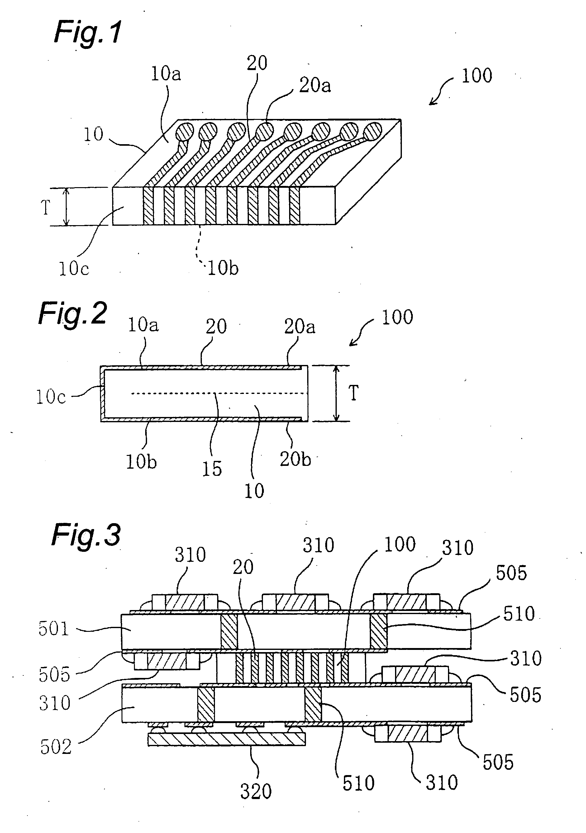
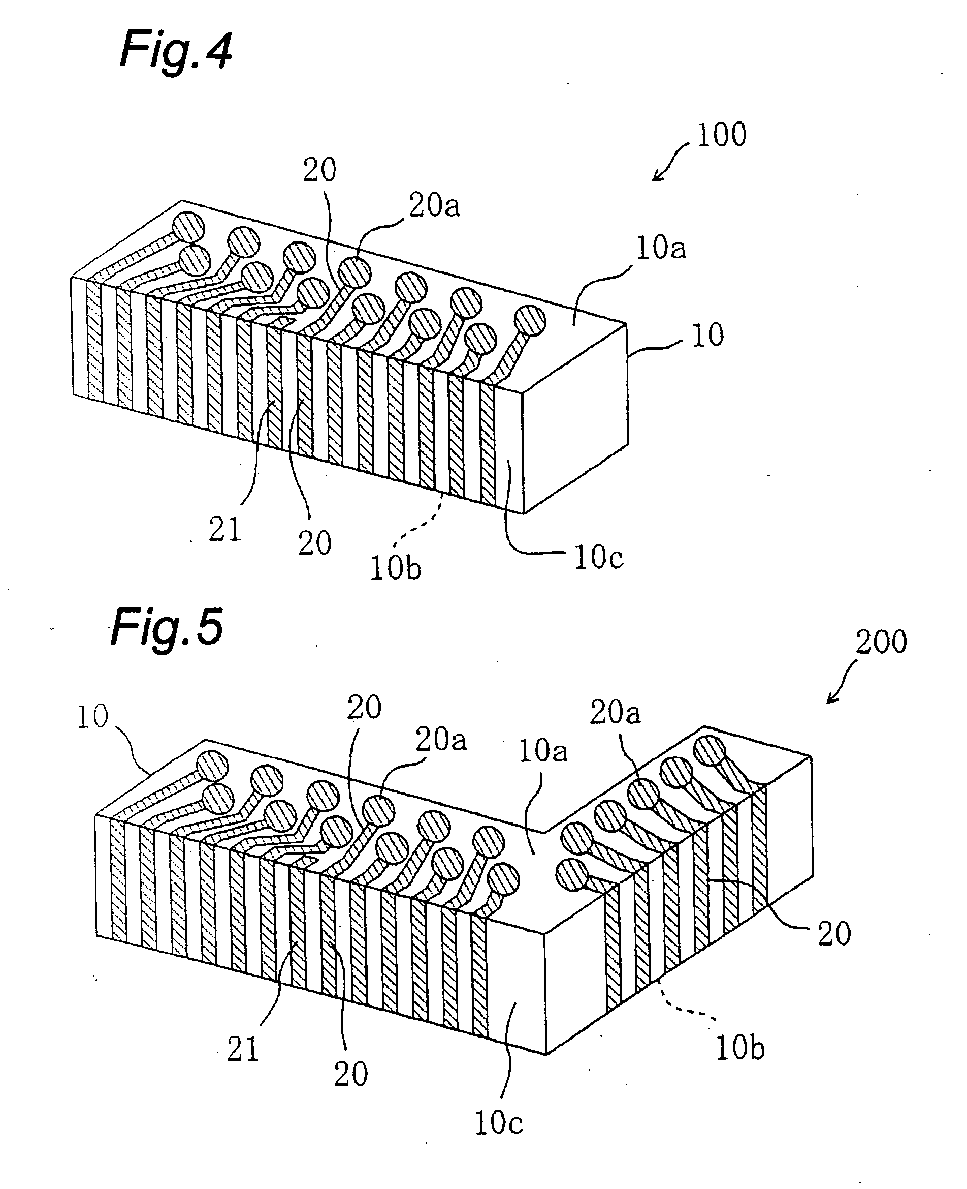
[0192] A connector sheet which is an embodiment of the connection member of the present invention is described as a first embodiment. FIG. 1 is a perspective view which schematically shows a connector sheet of the present invention and FIG. 2 shows a section where a U / L-shaped side wiring 20, lands 20a and 20b shown in FIG. 1 are placed. The connector sheet 100 of this embodiment has a sheet substrate 10 and a plurality of U / L-shaped side wirings 20. The sheet substrate 10 has an upper surface 10a, a lower surface 10b which is opposite to the upper surface 10a and a side surface 10c connecting the upper surface 10a and the lower surface 10b. One end portion 20a (land) of the U / L-shaped side wiring 20 exists on the upper surface 10a of the sheet substrate 10, the U / L-shaped side wiring 20 extends from the end portion 20a and passes the side surface 10c of the sheet substrate 10 and reaches the lower surface 10b, and the other end portion 20b of the wiring 20 exists on the lower surfa...

embodiment 2

[0251] Next, an embodiment of a mount assembly which is constructed by the connector sheet of the present invention and a circuit board is described below.

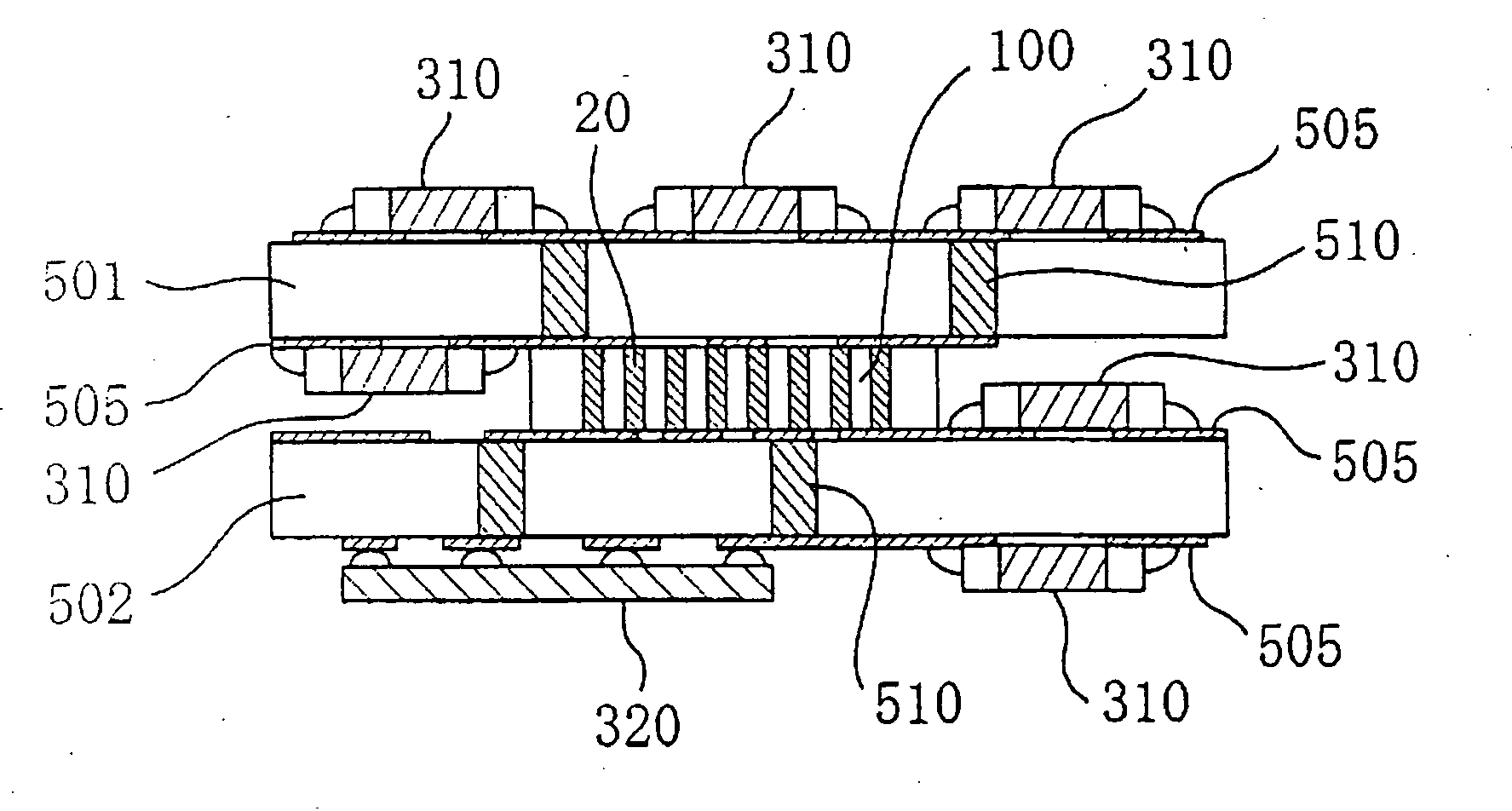
[0252]FIG. 14 shows a mount assembly wherein two circuit boards (for example, printed circuit boards) 503 and 504 are connected in a direction parallel to a principal surface by the connector sheet 100 of the first embodiment. The connector sheet 100 is disposed between the circuit boards 503 and 504 as shown in FIG. 14, and electrically connects them.

[0253] In the mount assembly shown in FIG. 14, each of the circuit boards 503 and 504 has wiring patterns 505 (conductor patterns). The wiring pattern 505 is also formed on at least a part of a side surface in each of the circuit boards 503 and 504. Further, a surface mount electronic component 310 and a semiconductor chip 320 are mounted on the wiring patterns 505.

[0254] In this mount assembly, the side-surface wiring portion of the U / L-shaped side wiring 20 which is located on o...

embodiment 3

[0268] Next, a connector sheet of another embodiment is described. In the case where the connection member of the present invention is provided as the connector sheet, the connector sheet may be constructed so that is has tackiness under a certain condition, and adhesiveness under another condition. Herein, the connector sheet having both of tackiness and adhesiveness is described.

[0269] For describing such a connector sheet, FIG. 1 is referred to for convenience. In the connector sheet 100 of this embodiment, both of the upper surface 10a and the lower surface 10b have tackiness under a first condition and adhesiveness under a second condition different from the first condition. Herein the first condition may be, for example, a temperature condition in a range of 0° C. to 80° C. More specifically, the first condition may mean that the upper surface 10a and the lower surface 10b are subjected to a temperature in this temperature range. The temperature of the first condition may be ...


PUM

PropertyMeasurementUnit
temperatureaaaaaaaaaa
areaaaaaaaaaaa
widthaaaaaaaaaa

Abstract

A connection member is provided which can be produced without a via-forming step. The connection member 100 includes an insulating substrate 10 which has an upper surface 10a, a lower surface 10b opposed to the upper surface 10b and a side surface 10c which connects these surfaces; at least one wiring 20 which extends from the upper surface to the lower surface through the side surface.

Description

TECHNICAL FIELD [0001] The present invention is related to a connection member for connecting circuit boards, or a circuit board and an electronic component and a method for producing the same and a mount assembly including the connection member. BACKGROUND OF THE INVENTION [0002] When a circuit board having a predetermined electrical circuit is connected electrically to another circuit board, they are, in general, electrically and mechanically connected by using a stacking connector. The stacking connector is disclosed, for example in Japanese Patent Kokai (Laid-Open) Publication No. 8(1996)-228059(A). [0003] Further, a technique for connecting electrically the circuit boards using an anisotropic conductive film (ACF) has been developed. Such a technique is disclosed, for example, in Japanese Patent Kokai (Laid-Open) Publication No. 5(1993)-174889(A) and Japanese Patent Kokai (Laid-Open) Publication No. 6(1994)-268345(A). Further, as shown in Japanese Patent Kokai (Laid-Open) Publi...

Claims


Application Information

Patent Timeline
Patent Type & Authority Applications(United States)
IPC IPC(8): H01R13/24H05K1/00H05K1/02H05K1/14H05K1/18H05K3/20H05K3/34H05K3/36H05K3/40
CPCH01R13/2414Y10T29/49208H05K1/0284H05K1/141H05K1/145H05K1/182H05K3/20H05K3/3442H05K3/361H05K3/366H05K3/368H05K3/403H05K2201/043H05K2201/048H05K2201/049H05K2201/055H05K2201/056H05K2201/09036H05K2201/10515H05K2201/10689H05K2203/302H01R12/52H01L2224/16225H01L2224/32225H01L2224/73204H05K1/0218Y10T29/49126Y10T29/49117H01L2924/00
Inventor ASAHI, TOSHIYUKIKARASHIMA, SEIJIICHIRYU, TAKASHINAKATANI, SEIICHINISHIYAMA, TOUSAKUHIRANO, KOICHISHIBATA, OSAMUNAKAYAMA, TAKESHISAITO, YOSHIYUKI
Owner PANASONIC CORP
Why Eureka
Try Eureka