Forming nanostructures

a nanostructure and nanotechnology, applied in the field of forming nanostructures, can solve the problems of inability to use the nanowire produced by this process in the industry, inability to automate the reliable manipulation of individual nanowires, and inability to collect and manipulate individual nanowires in a relatively time-consuming and laborious process, so as to achieve efficient formation and simple and cost-efficient installation

Inactive Publication Date: 2005-08-04
BAE SYSTEMS PLC
View PDF5 Cites 38 Cited by
  • Summary
  • Abstract
  • Description
  • Claims
  • Application Information

AI Technical Summary

Benefits of technology

[0027] Apparatus for providing the method for forming the nanowires or nanotubes does not include a gas input system and is consequently relatively simple and cost efficient to install.
[0028] For the formation of nanowires of the present invention, dimensions of the nanowires are not determined by a template material, for example a porous material such as alumina. Nanowires having consistent dimensions are efficiently formed without the need for the production of a template material having precise specifications.

Problems solved by technology

The nanowires formed in this process are often collected as a powder and the collection and manipulation of individual nanowires is a relatively time consuming, skillful and cost inefficient process.
To date there is no automated process for the reliable manipulation of individual nanowires.
This makes the use in industry of the nanowires produced by this process impractical.
This proves to be difficult if the dimensions of the pores are required to meet strict tolerances.
Despite this order and alignment, any manipulation of individual nanotubes is difficult.
Additionally, the relatively high temperature of the method prevents use of reagents which are unstable at such temperatures.
The use of acetylene gas is relatively hazardous as the gas is flammable, especially at relatively high temperatures.
Such relatively high temperatures prevent the use of materials which are unstable at such temperatures.
Additionally the use of acetylene or methane gas, which is commonly used in similar nanotube forming reactions, is relatively hazardous as the gas is flammable, especially at relatively high temperatures.

Method used


Image

  • Forming nanostructures
  • Forming nanostructures
  • Forming nanostructures

Examples


Embodiment Construction

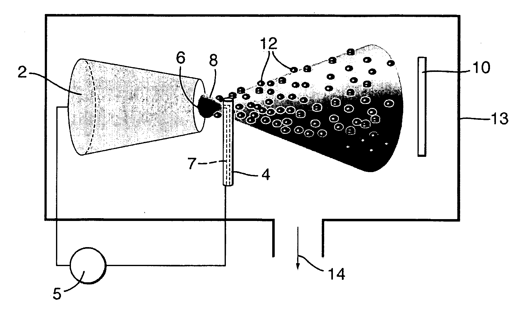
[0046]FIG. 1 shows schematically an apparatus for producing nanoparticles in accordance with an embodiment of the present invention.

[0047] The particles are of a metallic material and are provided for the method of forming a nanowire or a nanotube in accordance with embodiments of the present invention. In the case of the embodiments to be described in the following specification, the particles are nanoparticles, each of which has at least one dimension on the nano-scale. The metallic material in this embodiment is cobalt carbide (CO3C) which is an alloy of a ferromagnetic material which in this case is the metal cobalt (Co). The cobalt carbide is formed using a carbon arc technique.

[0048] The carbon arc technique involves a cathode 2 formed of graphite, and an anode 4 formed of a mixture of compressed graphite and cobalt powders. The mixture comprises approximately 30-50% by weight of cobalt. A voltaic arc is initiated between the cathode 2 and the anode 4 using a DC electric pow...


PUM

PropertyMeasurementUnit
temperatureaaaaaaaaaa

Abstract

A method of forming a nanowire comprising: providing nanoparticles of a metallic material; providing a vapour of fluorocarbon molecules by heating a solid polymer; depositing at least some of the carbon of said molecules onto an exterior of one of said particles to form a deposit of carbon which surrounds at least part of the exterior of said one particle and assembling further of said particles with said one particle to form an elongate configuration of material in the form of a nanowire. Similar methods of production of nanotubes are also disclosed.

Description

FIELD OF THE INVENTION [0001] The present invention relates to methods of forming nanostructures, particularly to methods of forming nanowires and nanotubes. BACKGROUND OF THE INVENTION [0002] Nanotechnology is defined by the Institute of Nanotechnology in the UK as “science and technology where dimensions and tolerances in the range of 0.1 nanometers (nm) to 100 nm play a critical role”. [0003] Research in the field of nanotechnology is a rapidly expanding industry and includes the production of nanostructures—structures which have at least one dimension at least approximately on the scale of 0.1 to 100 nm (referred to as the “nano-scale”). Two examples of nanostructures are nanowires and nanotubes, which each have a nano-scale cross section. [0004] Methods of forming nanostructures include methods based on the miniaturisation of technology developed initially at a scale greater than the nano-scale, and new methods for the formation of nanostructures from molecular elements. [0005]...

Claims


Application Information

Patent Timeline
Patent Type & Authority Applications(United States)
IPC IPC(8): C01B31/02C01B31/30C04B35/622C25D1/04
CPCB82Y30/00C01B31/303C04B35/62227C04B2235/5284C04B2235/405C04B2235/5264C04B35/62277C01B32/914
Inventor HAQ, SAJADALEXANDROU, IOANNISAMARATUNGA, GEHAN A JANG, KHAI H
Owner BAE SYSTEMS PLC
Why Eureka
Try Eureka