
Process for the catalytic partial oxidation of H2S using staged addition of oxygen

a technology of partial oxidation and h2s, which is applied in the direction of sulfur compounds, physical/chemical process catalysts, sulfur preparation/purification, etc., can solve the problems of reducing the efficiency of sulfur removal plants, reducing the market value of gas, so as to reduce pollution of the air, reduce pollution, and reduce the effect of sulfur removal

Inactive Publication Date: 2005-07-21
CONOCOPHILLIPS CO
View PDF54 Cites 13 Cited by
  • Summary
  • Abstract
  • Description
  • Claims
  • Application Information

AI Technical Summary

Benefits of technology

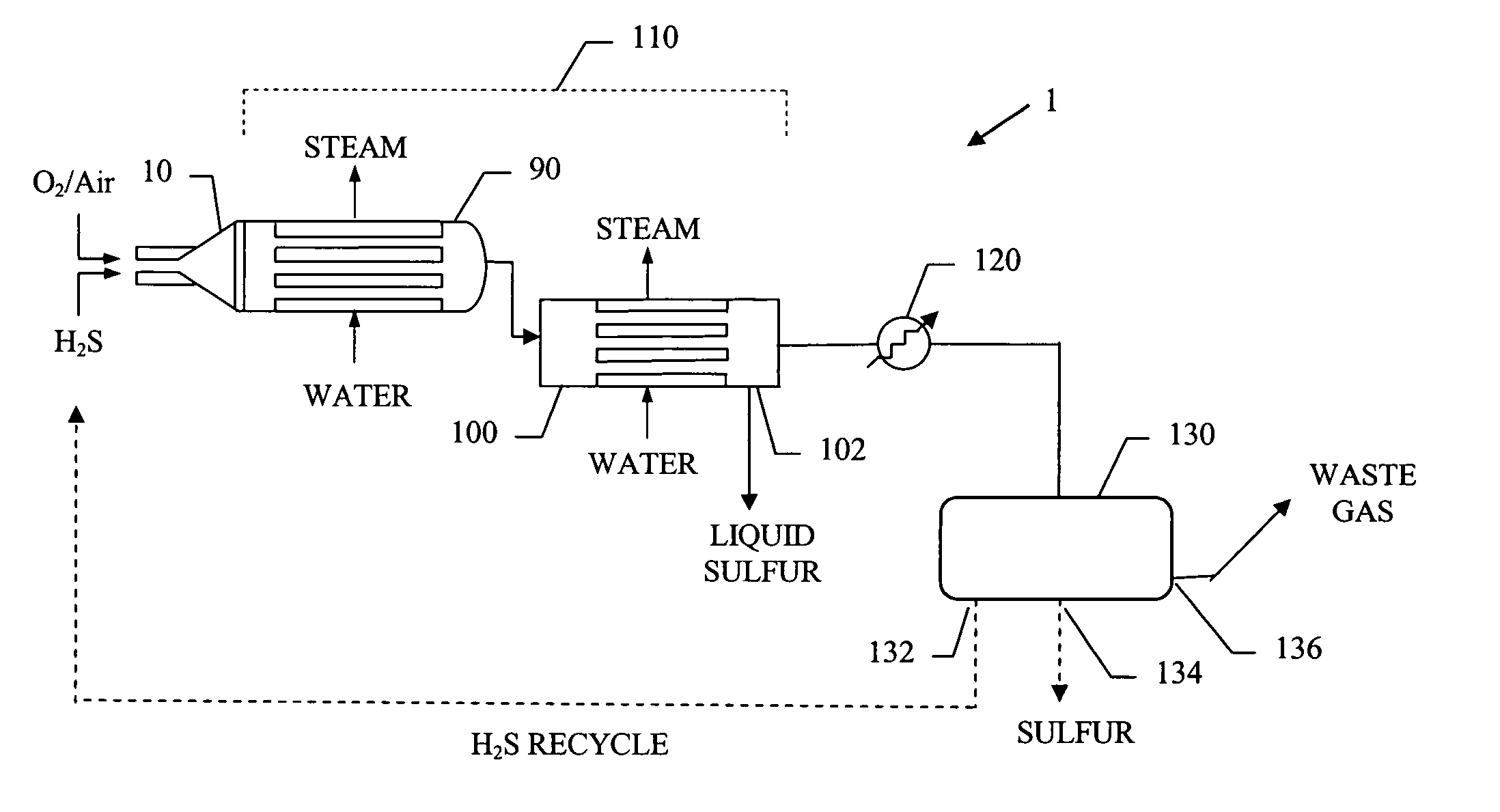
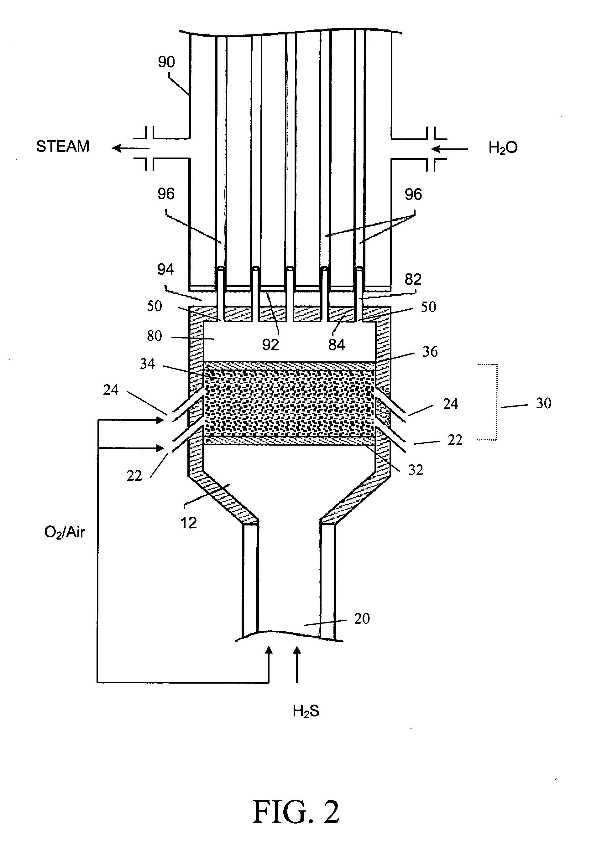
[0018] The present invention provides a process and apparatus in which H2S-containing streams, with H2S concentrations ranging from very low to high (e.g., about 1% to 100% (by volume)), are converted to elemental sulfur and water. The basic SPOC™ process has been modified to improve the total H2S conversion and the amount of S0 recovered. The improvement includes staged air, oxygen or oxygen-enhanced air addition to the reactor whereby the amount of oxygen added to the front of the catalyst bed is such that SO2 formation is minimized, preferably, no more than 10% of the sulfur in the feed is converted to SO2. Since this also limits the H2S conversion, the oxygen is added along the catalyst bed in smaller than stoichiometric oxygen / H2S ratios to achieve higher overall H2S conversion and S0 yields, and lower SO2 yields. The reactor is still operated in short contact time mode (i.e., 200 milliseconds or less). H2S is converted to S0 by the catalytic partial oxidation of H2S according to the reaction H2S+½ O2→½ Sx+H2O  (5) (wherein x=2, 6 or 8, depending on temperature and pressure). The total or nearly complete conversion of the H2S component to elemental sulfur is achieved, and the yield of recovered elemental sulfur is thereby enhanced. Since complete oxidation to SO2 also increases the reaction temperature, staged oxygen addition at sub-stoichiometric oxygen / H2S ratios will help minimize the undesired reactions occurring as a result of high temperatures. Also, it is possible to reduce the total amount of oxygen used in the process without making any other changes to the catalyst composition or overall process.
[0019] The new staged air / oxygen catalytic partial oxidation process and system (termed SPOC-III™) offers significant advantages for more efficiently recovering elemental sulfur from H2S-containing streams and for reducing pollution of the air by H2S from natural gas wells or emissions from petroleum refinery vent stacks, compared to conventional sulfur recovery systems. Another advantage of the present apparatus and process is that it is possible to make a relatively compact sulfur removal plant. The new apparatus and process also make it more economically and environmentally feasible for refineries to utilize high sulfur crude oils by providing for the efficient recovery of sulfur from the accompanying H2S waste gas.

Problems solved by technology

The removal of sulfur from natural gas is a particular concern because utilization of the enormous supply of natural gas existing in underground reservoirs all over the world is hindered due to the presence of naturally-occurring H2S along with the methane and other light hydrocarbons that make up natural gas.
Some natural gas formations contain only a relatively small concentration of H2S, yet even those types of natural gas wells typically remain shut-in today because the cost of removal of the H2S using existing methods and apparatus exceeds the market value of the gas.
A further deterrent to full utilization of H2S-containing natural gas resources is the corrosive effect of the H2S component of liquefied natural gas on the transportation pipes and storage vessels that are needed to bring the H2S-containing natural gas from remote locations to existing sulfur treatment plants.
Sulfur recovery was low and the highly exothermic reaction was difficult to control.
The Claus-type processes are not suitable for use in cleaning up hydrogen or light hydrocarbon gases (such as natural gas) that contain H2S, however.
Not only is the hydrocarbon content lost in the initial thermal combustion step of the Claus process, but carbon, carbonyl sulfide and carbon disulfide byproducts cause catalyst fouling and dark sulfur.
Moreover, carbonyl sulfide is difficult to convert to elemental sulfur.
The major problem with the Claus process is the inherent equilibrium constraint of the Claus reaction caused by the necessity of generating the SO2 intermediate.
Usually these catalytic oxidation processes are limited to Claus tail gas operations or sulfur recovery from streams that have very low H2S content (i.e., about 1-3%).
Low concentration H2S streams will not produce enough energy release from oxidation to sustain a flame as in a thermal reactor stage.
The existing catalytic oxidation technologies are thus limited to low concentration H2S-containing streams using non-refractory lined vessels.
Existing processes are also limited in the amount of sulfur that can be handled because the heat transfer equipment needed to remove the heat of reaction becomes extremely large due to the low temperature differential between the process and the coolant streams.
These processes are also limited in the amount of sulfur recovered due to the heat removal constraints at low temperatures and the need to maintain low temperatures to keep the liquid from boiling.
For at least these reasons, existing direct oxidation processes have not proved to be viable substitutes for the Claus process in most industrial applications.
As mentioned above, conventional direct oxidation methods are applicable to sour gas streams containing relatively small amounts of H2S and large amounts of hydrocarbons, but are not particularly well suited for handling more concentrated acid gas streams from refineries.
For this reason direct oxidation methods have been generally limited to use as tail gas treatments only, and have not found general industrial applicability for first stage sulfur removal systems from gases containing large quantities of H2S.
Even though the Claus process still finds widespread industrial use today for recovering elemental sulfur from H2S that is generated in many industrial processes, such as petroleum refinery processes, and for reducing sulfur emissions from refineries, the Claus process is generally viewed as relatively costly for routine use on a commercial scale.
A number of TGTUs are usually needed to achieve the 99+% conversion of H2S to S0, and involves a large initial investment and appreciable maintenance costs.
Significant capital and maintenance costs are associated with conventional multi-stage treatment units.
Conventional desulfurization operations are also not practical for use at small operations such as remote well sites or on natural gas producing off shore oil platforms.

Method used


Image

  • Process for the catalytic partial oxidation of H2S using staged addition of oxygen
  • Process for the catalytic partial oxidation of H2S using staged addition of oxygen
  • Process for the catalytic partial oxidation of H2S using staged addition of oxygen

Examples


example 1

[0077] A catalyst having the composition 1% Rh, 4% Pt, 3% Mg on fused alpha-alumina pills, 4 grams was prepared and tested as described above. The H2S flow rate was 850 ml / min, or 0.85 SLPM, and the reactant gas preheat temperature was 450° F. (232° C.). The results of those tests are shown in Table 3.

TABLE 3Effect of Air / H2S Ratio on H2S Conversionand Product SelectivityAir / H2S% H2S% Sulfur% SO2% H2% S0% SO2RatioConversionYieldYieldYieldSelectivitySelectivity2.3784.4872.7911.666.6586.1613.802.2683.7673.1710.556.4087.3612.602.1682.7773.659.096.4688.9810.982.0781.6473.757.866.5690.339.631.9779.9773.206.746.6691.538.421.8785.6182.093.504.2995.894.091.7776.2571.614.606.7893.926.041.6774.4570.713.716.9594.984.981.5772.1169.083.016.9595.794.17

Catalyst: 1% Rh, 4% Pt, 3% Mg on fused alpha-alumina pills

example 2

[0078] A catalyst having the composition 1% Rh, 4% Pt, 3% Mg on fused alpha-alumina pills, 4 grams was prepared and tested as described above. The H2S flow rate was 950 ml / min, or 0.95 SLPM, and the reactant gas preheat temperature was 450° F. (232° C.). The results of those tests are shown in Table 4.

TABLE 4Effect of Air / H2S Ratio on H2S Conversionand Product SelectivityAir / H2S% H2S% Sulfur% SO2% H2% S0% SO2RatioConversionYieldYieldYieldSelectivitySelectivity2.7685.7566.3119.417.8077.3322.642.6685.1167.1717.917.9778.9321.042.5584.3968.0516.318.1580.6419.332.4683.5168.6414.878.3982.1917.812.3681.5967.5014.089.0082.7417.262.2581.3069.1812.108.8985.0914.882.1780.1069.3110.779.0086.5213.452.0678.8769.459.408.9188.0511.921.9777.0968.868.218.7189.3210.651.8774.8367.996.828.1790.869.111.7772.2266.395.817.4191.928.051.6769.0263.995.016.4692.717.261.5765.2860.914.355.3793.306.661.4761.2457.383.844.2293.706.261.3757.7954.303.473.1193.966.001.2754.4250.963.452.2193.636.33

Catalyst: 1% Rh, 4%...

example 3

[0079] A catalyst having the composition 4% Pt, 1% Rh, 3% Mg on MgO granules, 4 grams, was prepared and tested as described above. The H2S flow rate was 1,050 ml / min, or 1.05 SLPM, and the reactant gas preheat temperature was 450° F. (232° C.). The results of those tests are shown in Table 5.

TABLE 5Effect of Air / H2S Ratio on H2S Conversionand Product SelectivityAir / H2S% H2S% Sulfur% SO2% H2% S0% SO2RatioConversionYieldYieldYieldSelectivitySelectivity2.3784.6173.8010.814.8187.2212.782.2783.9873.7710.186.3087.8512.122.1782.4173.269.136.5888.8911.082.0780.9472.937.996.6190.119.871.9779.1672.376.766.6191.438.541.7775.7470.725.016.3493.366.611.5771.5968.283.296.1595.374.601.4868.3565.792.536.2396.263.701.3865.6763.642.006.1696.913.05

Catalyst: 4% Pt, 1% Rh, 3% Mg on MgO granules


PUM

PropertyMeasurementUnit
Temperatureaaaaaaaaaa

Abstract

A multistage oxygen-added catalytic partial oxidation process and apparatus for converting H2S in an acid gas stream to elemental sulfur and water are disclosed. Each staged addition of oxygen or air at the top of the catalyst bed and at points along the catalyst bed maintain oxygen-limited H2S catalytic partial oxidation conditions whereby incidental SO2 production is minimized.

Description

BACKGROUND OF THE INVENTION [0001] 1. Technical Field of the Invention [0002] The present invention generally relates to sulfur recovery processes and to apparatus for removing sulfur from H2S-containing gas streams and producing elemental sulfur. More particularly, the invention relates to H2S catalytic partial oxidation processes that include staged addition of oxygen, and to apparatus for carrying out such processes. [0003] 2. Description of the Related Art [0004] Sulfur removal from H2S-containing gas streams is a field of endeavor that is receiving a great deal of attention today, particularly in the petroleum industry. Considerable quantities of H2S are created from the refining of petroleum in processes such as crude oil hydrodesulfurization, gasification of coal and desulfurization of natural gas. The removal of sulfur from natural gas is a particular concern because utilization of the enormous supply of natural gas existing in underground reservoirs all over the world is hi...

Claims


Application Information

Patent Timeline
IPC IPC(8): B01J8/02B01J8/06C01B17/04
CPCB01J8/025B01J8/067C01B17/0465C01B17/046B01J2208/00176
Inventor RAMANI, SRIRAMKELLER, ALFRED E.
Owner CONOCOPHILLIPS CO
Learn More