
Screw head formation

a screw head and head technology, applied in the direction of screws, geometric arrangements, bolts, etc., can solve the problems of increasing costs, not being able to form in a single strike, and not being able to form deep recesses without, so as to reduce the tendency for tips and achieve the effect of considerable skill and patien

Inactive Publication Date: 2005-07-21
UNI SCREW A UK CORP
View PDF13 Cites 4 Cited by
  • Summary
  • Abstract
  • Description
  • Claims
  • Application Information

AI Technical Summary

Benefits of technology

[0020] 2) with such a shallow depth of recess the recess can be formed by a single strike of the punch which renders the screw relatively inexpensive to manufacture. Moreover, the punch is likely to last for in excess of 100,000 strikes, which likewise leads to cost reduction. Further, although not as a result of this aspect of the invention, the punch can be made relatively inexpensively by a method described further below and this also, impacts the cost of manufacture of the screw.
[0021] 3) with such accurate tolerance and low draw the tendency of the driver to cam-out or round-out of the recess is reduced, even with such a shallow recess.
[0022] 4) with such a shallow recess, and the other cost factors mentioned above, the head can economically be formed on counter-sunk wood screws so that the benefits first envisaged by GB1150382, and more recently in GB2285940, can at least be realised.
[0039] By virtue of the three degrees of freedom of each cutting element it takes considerable skill and patience to adjust the cutting elements to reach the desired precision of position. The desired precision is in the order of ±2.5 microns in each direction. However, once the system is set up, it is simply a matter of turning the CNC machine on and letting it run. Once set-up, operation and production of punches can be automatic.
[0042] This chamfer does not greatly reduce the area of the faces of the recess that transmit torque between a correspondingly shaped tool inserted into the recesses. But it does have a marked effect on the lifetime of a punch that forms the recesses by cold-heading. As a consequence, the recesses can be deeper than would otherwise be possible, so regaining any lost area by virtue of the chamfer.

Problems solved by technology

However, such a deep recess can neither be formed without substantial draw (to permit release of the punch after forming of the recess), nor can it be formed in a single strike.
But the multiple strike using progressively larger punches does result in greatly increased costs.
In this market, cost is vitally important.
However, this is not only because of the cost associated with the other polygon recesses.
Despite the apparent advantages of the multi-tiered screw-head design, however, they have not yet succeeded in penetrating the market.
The reason for this is simply that hitherto it has not been possible to put the idea into practical, that is to say, commercial, effect.
Otherwise process times and punch costs (for example, if two different punches. are required) render the operation prohibitively expensive; 2) punches must have a strike capacity in excess of 100,000, or thereabouts, for the same reason; and 3) punches must be inexpensive to manufacture.
One of these problems is that, with parallel sided recesses, punches tend to break because of the elastic grabbing of the tip of the punch (which tip forms the deepest, smallest recess) as the punch is withdrawn.

Method used


Image

  • Screw head formation
  • Screw head formation
  • Screw head formation

Examples


Embodiment Construction

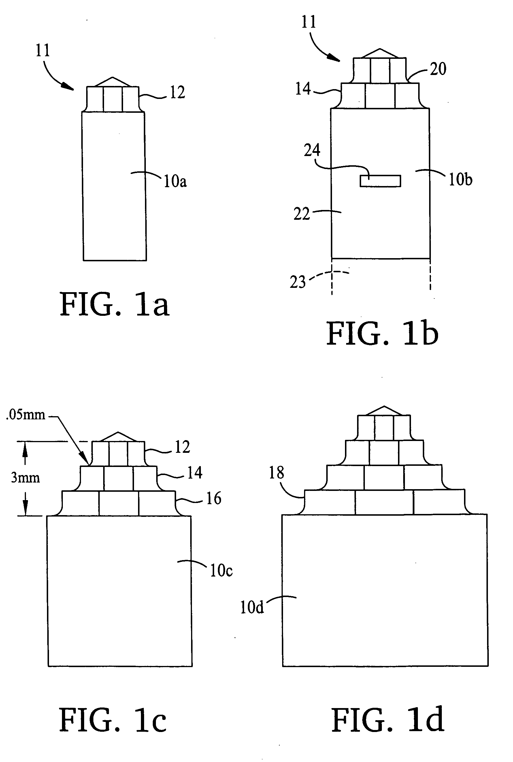
[0050] With reference to FIG. 1, each drawing illustrates a punch 10a,b,c,d having respectively one, two, three and four tiers 12,14,16,18. Each tier has a height of approximately 1 mm. Each tier has a fillet 20 at its base serving to support it. The fillet has a radius of approximately 0.05 mm. The punch 10 is made by cutting the profile of the head from a bar stock 22,23 using a profilating CNC machine described further below. As well as cutting the profile 11, the CNC machine will also cut a locating slot 24 and part the formed punch 10b from the remaining bar stock 23.

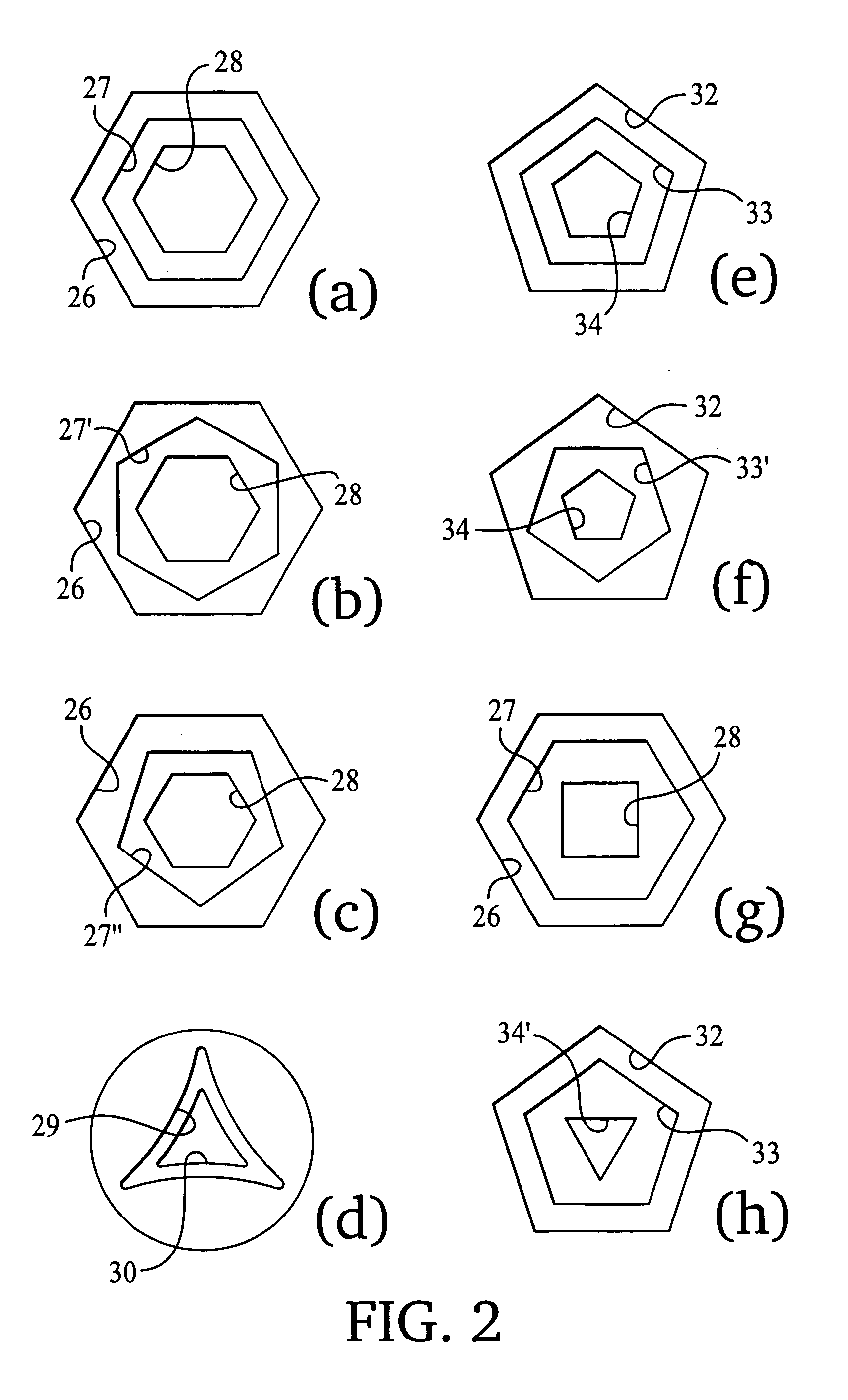
[0051] When the punch 10 is fitted in a cold heading device, and driven into the head of a screw in an axial direction, recesses having the profiles of the sort illustrated in FIG. 2 are formed.

[0052]FIG. 2a is a three-recess design with concentric and aligned hexagons 26,27,28. FIG. 2b is similar to FIG. 2a, except that the middle recess 27′ is rotationally offset with respect to recesses 26,28 by 30°.

[0053]FIG...


PUM


Abstract

The screw has two or three non-circular super-imposed recesses. The depth of each recess is less than 1.2 mm and there is a less than 1° of draw in each recess. The screw head recess is formed using a punch (10) in a cold-heading process. The punch is formed in a profilating CNC machine, cutting the profiles (12, 14, 16) of the punch to a tolerance of better than ±0.025 mm. A method of manufacture of a cold-forming punch for such a screw comprises providing a profilating head as one of the tools on a turret mounted adjacent the chuck in the CNC machine. The profilating head has several cutting elements, each being adjustable with respect to one another: axially, radially and angularly.

Description

BACKGROUND OF THE INVENTION [0001] The present invention relates to a form of screw head for a screw fastener, and to a tool to drive such screw. In particular, the invention relates to a method of manufacture of a punch for cold forming such screw head. [0002] GB1150382 appears to be the first patent to recognise the benefits of a multi-tiered screw head design that has stepped tiers between a deep central recess and a wider top recess, the recess having sides parallel a central axis of the screw. Such recesses are effective at reducing “cam out”. Furthermore, the recess can be deeper in the head of the screw without weakening the connection between the shaft of the screw and its head. This is because, at its deepest, where the countersink is narrowest or the transition between head and screw shank occurs, the recess is smallest. [0003] GB2285940 elaborated on this principle and pointed out that the same screwdriver could be employed to drive large screws (having several tiers of r...

Claims


Application Information

Patent Timeline
IPC IPC(8): B21K1/46B21K5/20B23C5/24B23Q27/00F16B23/00G05B19/18
CPCB21K1/463B21K5/20B23C5/2462B23Q27/00G05B2219/45137F16B23/00F16B23/0038G05B19/186B25B15/008
Inventor BROOKS, LAWRENCE ANTONY
Owner UNI SCREW A UK CORP
Learn More