Eureka AIR delivers breakthrough ideas for toughest innovation challenges, trusted by R&D personnel around the world.

System and process for solid-state deposition and consolidation of high velocity powder particles using thermal plastic deformation

a technology of thermal plastic deformation and solid-state deposition, which is applied in the direction of lighting and heating apparatus, coatings, combustion types, etc., can solve the problems of low deposition efficiency of gabel and tapphorn, ineffective commercial application economic viability of coating applicators and processes, and inefficient accelerating powder particles to high speeds. , to achieve the effect of high velocities, no surface pretreatment, and excellent adhesion

Inactive Publication Date: 2005-07-14
INNOVATION TECH INC
View PDF1 Cites 112 Cited by
  • Summary
  • Abstract
  • Description
  • Claims
  • Application Information

AI Technical Summary

Benefits of technology

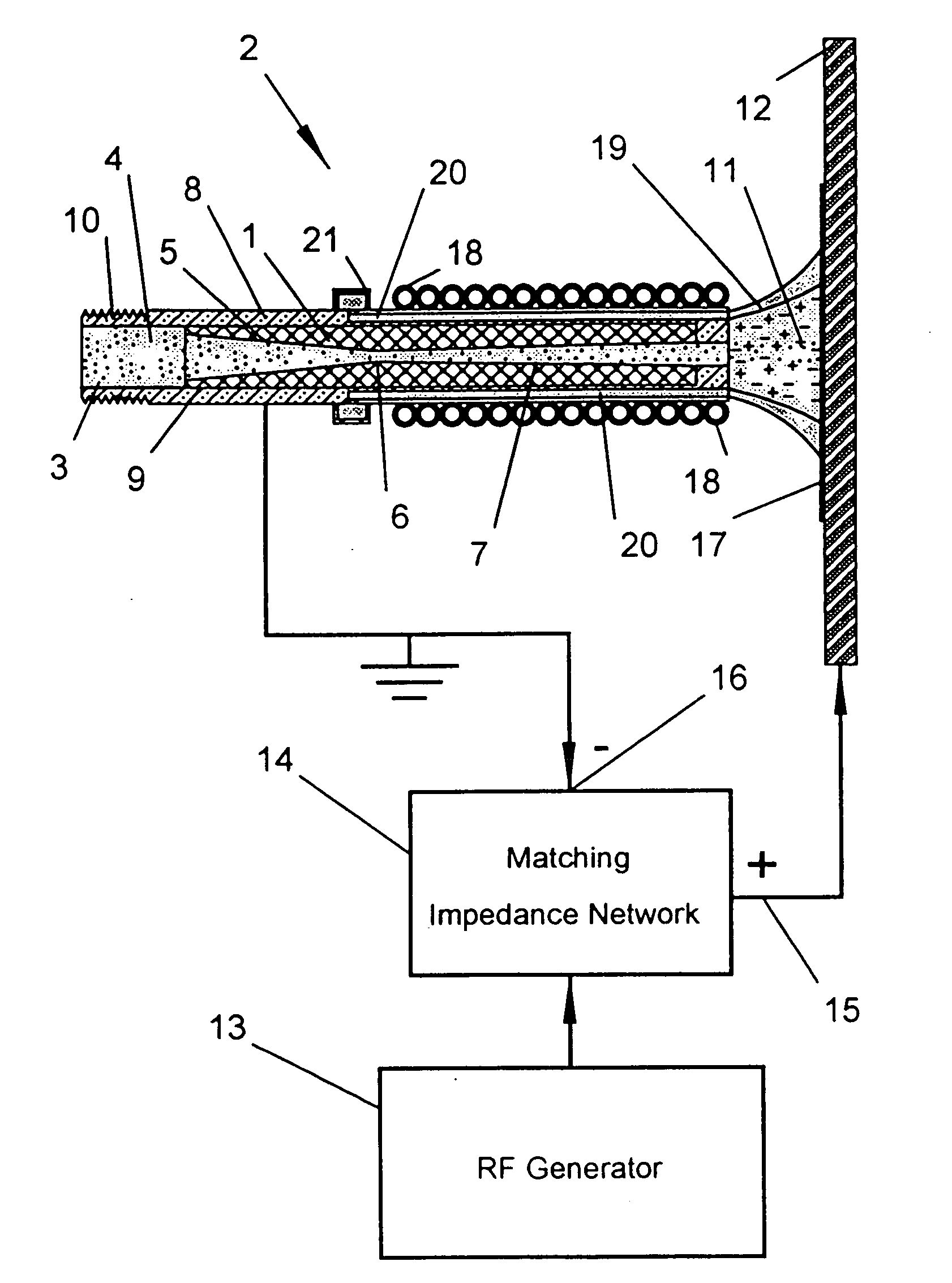
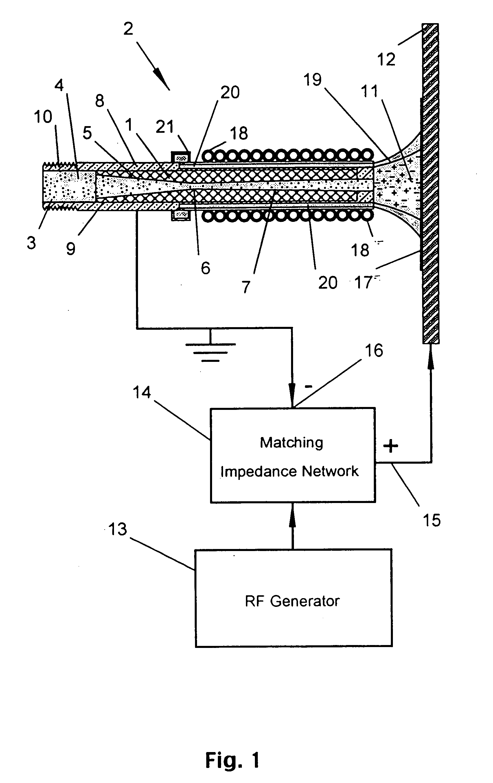
[0026] Simultaneously coupling the kinetic energy of the particles transferred to the impact process with the reduction in yield strength of said powder particles and substrate, induced by heating (thermal-plastic conditioning), permit solid-state deposition and consolidation of coatings, spray forming of parts, or joining of various materials via thermally dependent plastic deformation. By controlling the velocity of the impact process in combination with thermal-plastic conditioning the material properties can be tailored to specific requirements. For example, the severe plastic deformation induced by the impact process is responsible for the creation of observed nanostructures within the microstructure of the consolidated powder particles. Thermal plastic conditioning of the powder particles allows these nanostructures to be modified through enhanced dynamic recovery of dislocation densities. In addition, the chemical potentials of the consolidated materials are modified by high-pressure confinements induced by residual stresses associated with severe plastic deformation. These modified chemical potentials effect the chemical reaction rates for controlling the properties of metal matrix composite functionally formed during in-situ fabrication of strengthening phases within a metallic matrix. This process yields high quality consolidations with low porosity, low oxidation, and minimal thermal distortion. The process also yields depositions with unique nanostructure and microstructure and permits spray forming, joining, and fusing of various materials. The deposition is sprayed over the substrate by translating the friction-compensated sonic nozzle in raster fashion over the substrate at relatively short standoff distances and at speeds that permit depositions and consolidations to a desired thickness. More intelligent translations of a plurality of friction-compensated sonic nozzles under robotic control permit rapid sterolithographic formation of near net shape parts and components.
[0051] Finally, the apparatus and process of this invention permits co-deposition of powders to functionally form in-situ and ex-situ composites. In one example, a metallic powder (e.g., aluminum) is co-deposited with an ex-situ strengthening agent selected from a group comprising silicon, carbide, boron carbide, alumina, tungsten carbide, or mixtures thereof to form a particle reinforced metal matrix composite that has homogeneous dispersion of the strengthening agent. In another example the invention permits the co-deposition of metallic powders into a consolidated composite that is subsequently transformed (final heat treatment) into an in-situ particle reinforced metal matrix composite after finish machining. A variation of this example permits the co-deposited of metallic powders with other metallic or nonmetallic powder mixtures to tailor coatings or spray formed materials with unique properties. For instance, by co-depositing mixtures of aluminum and chromium powders (equal parts by weight), an electrically conductive strip can be applied to steel that has a tailored electrical resistivity (i.e., typically 72 μΩ-cm), excellent corrosion resistance (20 years in salt water immersion at 70° F) and an excellent adhesion strength on steel.

Problems solved by technology

The coating applicator and process disclosed in U.S. Pat. No. 5,795,626 issued to Gabel and Tapphorn has a low deposition efficiency, which is attributed to the high elastic response of triboelectrically charged powder particles at ambient temperature that have not been thermal plastically conditioned to induce plastic deformations.
Thus, the coating applicator and process disclosed in U.S. Pat. No. 5,795,626 is not economically viable for commercial applications without thermal plastically conditioning the powder particles to induce plastic deformations.
Supersonic nozzles, however are extremely inefficient for accelerating powder particles to high speeds because the flow expansion process for achieving high supersonic gas speeds inherently decreases the drag force on the powder particles.
Specific examples in the specification indicate that the deposited material does not exceed 100° C. Thus, the Alkhimov et al. patent is limited in its claims in terms of controlling the consolidation physical state of the applied coatings and the process results in coatings with low deposition efficiency and high residual stresses.
Both of these patents restrict the prior art to applications using supersonic jets.
Furthermore, the supersonic flow specified in the prior art is very inefficient in terms of accelerating powder particles.
The complexity, inherent in the prior art in plasma guns, increases the cost of these devices for commercial applications.
More importantly these conventional plasma guns wastes a large quantities of energy in the form of heat that must be carried away by the cooling water used to keep the electrodes and nozzles from melting or eroding.
Plasma cutting torches (e.g., U.S. Pat. No. 6,002,096 issued to Hoffelner et al.) frequently use a DC transfer-arc to melt or burn (oxidize) a substrate, but this prior art is restricted to cutting applications and does not claim a method for coating, spray forming, joining, or fusing materials using entrained powder particles in the carrier gas.
Plasma heaters and burners have been used to heat and ionized gas (e.g., U.S. Pat. No. 3,601,578 issued to Gebel et al.) and to improve combustion efficiency (e.g., JP 60078205 A issued to Toshiharu), but such devices have not been used to thermally treat particles prior to depositions of coatings.
These patents do not teach a method for controlling the deposition and consolidation states of coatings at temperatures below the material melting point.
Furthermore, these low-pressure plasma guns or torches have the commercial disadvantage of requiring costly vacuum chambers and equipment to produce the plasma stream.
If the temperature of the particle is too low, insufficient deformation of the particle occurs upon impact resulting in poor quality coatings with poor bonds.
The powder is injected into a temperature controlled plasma stream to heat-soften or plasticize, but not for a sufficient time to liquefy or vaporize.
Cladding techniques have been used for modifying the surface of aluminum alloys for many applications, but the process is costly and is primarily amenable to sheet stock.
Attempts to use thermal and plasma spray methods for depositing thermally softened or molten braze alloys onto aluminum alloys as disclosed in U.S. Pat. No. 4,732,311 issued to Hasegawa et al. have been largely unsuccessful because of low adhesion (which causes flaking of the coating material during subsequent forming steps).
However, this factor is alone is insufficient to achieve metallurgical bonding of the powder particles during impact.
Heating the entrained powder particles reduces the modulus of rigidity and decreases the yield strength of the particles, which in turn enhances plastic deformation during impact at low flow stress levels.

Method used


Image

  • System and process for solid-state deposition and consolidation of high velocity powder particles using thermal plastic deformation
  • System and process for solid-state deposition and consolidation of high velocity powder particles using thermal plastic deformation
  • System and process for solid-state deposition and consolidation of high velocity powder particles using thermal plastic deformation

Examples


example 1

[0112] Referring now to FIGS. 8 and 9, a bulk powder 52 is placed into hopper 48 of the powder fluidizing unit 47 and the pressure of carrier gas 4 injected into inlet port 50 is regulated to a value in the range of 50-250 psig. Carrier gas 4 may include but is not limited to air, argon, carbon tetrafluoride, carbonyl fluoride, helium, hydrogen, methane, nitrogen, oxygen, silane, steam, sulfur hexaflouride, or mixtures thereof in various concentrations. Carrier gas 4 is injected into fluidizing ports 62 and movable fluidizing port 64 of FIG. 9 and regulated to a higher pressure up to 500 psig. The differential pressure between carrier gas 4 injected into fluidizing ports 62 and carrier gas 4 injected into inlet port 50 is regulated at specific values depending on the location and depth of each fluidizing port 62 relative to bulk powder 52. Carrier gas 4 injected into a fluidizing port 62 at the greatest depth in bulk powder 52 has the largest differential pressure and is typically 2...

example 2

[0138] Thermal performance of multi-layer coatings 76 applied with the applicator and process of this invention were tested by brazing core aluminum alloy substrates and metallurgically evaluated to determine the porosity of the joint and to examine the substrate 12 adhesion. The thermal performance was assessed by measuring the thermal diffusivity of a typical braze joint.

[0139] A 3000 series aluminum alloy was coated with thermal-plastic conditioned 4047-alloy powder (no undercoat) to a thickness of 40 micrometers using the applicator and process described in this invention. Additionally, a flux coating 79 of potassium fluoro-aluminate salt powder was heated and embedded into the semi-porous structure of the 4047-alloy braze filler coating 78 using the applicator and process described in this invention. This multi-layer coating 76 was tested by fabricating a braze joint. The joint exhibits low porosity in combination with the excellent metallurgical bonding to ensure good thermal...

example 3

[0143] Referring again to FIGS. 4 and 5, the application and process of the invention provides a method for spray forming materials onto a substrate 12 or for spray forming a raised fillet 22 between two separate pieces 23 and 24 that are joined by fusing materials. Thus, depending on the choice of powder particles 3, substrate 12 materials, and applied RF generator 13 power the apparatus and process of this invention can be used not only for spray forming of materials, but also joining similar or dissimilar materials by fusion.

[0144] The friction-compensated sonic nozzle 2 (referring to FIGS. 4, 5, and 6) may also be used to spray-form metals and metal-matrix composites into near-net shape. The near-net shape is enabled by robotic control of friction-compensated sonic nozzle 2 such that various geometrical shapes are spray-formed onto substrate 12 with each pass. Build-up is controlled by the dwell time over specific locations. Dwell times can range from a few milliseconds to time...


PUM

PropertyMeasurementUnit
sizeaaaaaaaaaa
particle sizesaaaaaaaaaa
temperatureaaaaaaaaaa

Abstract

The invention relates to an apparatus and process for solid-state deposition and consolidation of powder particles entrained in a subsonic or sonic gas jet onto the surface of an object. Under high velocity impact and thermal plastic deformation, the powder particles adhesively bond to the substrate and cohesively bond together to form consolidated materials with metallurgical bonds. The powder particles and optionally the surface of the object are heated to a temperature that reduces yield strength and permits plastic deformation at low flow stress levels during high velocity impact, but which is not so high as to melt the powder particles.

Description

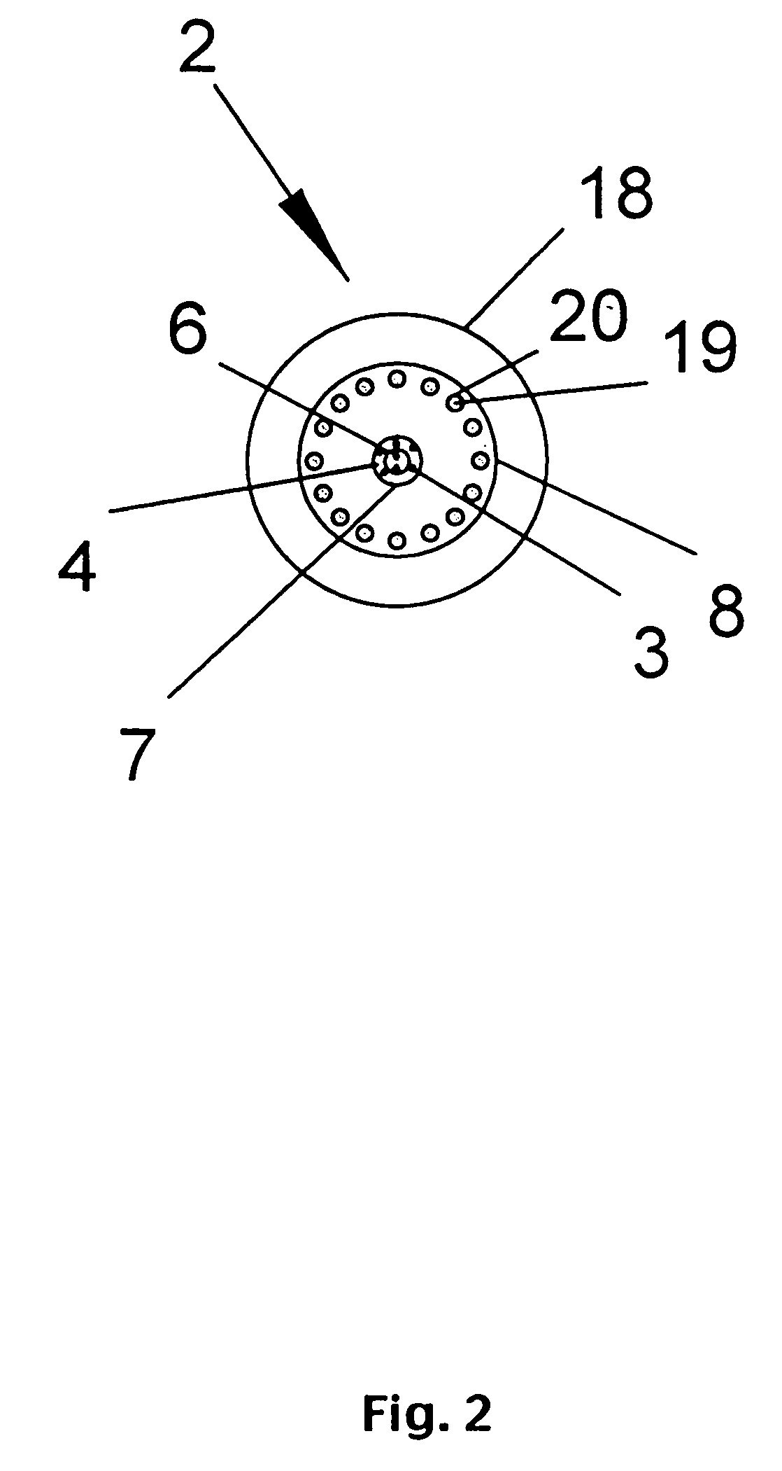
BACKGROUND [0001] 1. Technical Field [0002] The present invention relates to an apparatus and process for solid-state deposition and consolidation of high velocity powder particles entrained in a subsonic or sonic gas jet onto a substrate material. Upon impact the powder particles undergo plastic deformation which permits adhesive bonding to the substrate and inter-particle metallurgical bonding. This adhesive and cohesive bonding permits coatings of substrates and spray forming of near net shape components and parts. The basic embodiment of the invention uses a friction-compensated sonic nozzle to accelerate powder particles to high velocities with several methods for heating (thermal-plastic conditioning) the powder particles and substrate to temperatures sufficiently high to reduce the yield strength during impact and permit plastic deformation at low flow stress levels. One method of the heating the powder particles and substrate uses an ambient pressure thermal-transfer plasma ...

Claims


Application Information

Patent Timeline
Patent Type & Authority Applications(United States)
IPC IPC(8): B05B7/14B05B7/22B05B15/04C23C24/04
CPCB05B7/144B05B7/226B22F7/02C23C24/04B22F3/001B05B15/04B05B12/16H05H1/30C23C4/00
Inventor TAPPHORN, RALPH M.GABEL, HOWARD
Owner INNOVATION TECH INC
Why Eureka
Eureka Blog
Learn More