
Method of manufacturing solid electrolyte battery

Inactive Publication Date: 2005-06-23
NISSAN MOTOR CO LTD
View PDF5 Cites 152 Cited by
  • Summary
  • Abstract
  • Description
  • Claims
  • Application Information

AI Technical Summary

Benefits of technology

[0007] However, with the solid electrolyte battery disclosed in Japanese Patent Application Laid-Open No. 2002-305028, interfaces are present in respective contact surfaces of a positive electrode active material layer, a solid electrolyte layer and a negative electrode active material layer, resulting in an issue with an interference in the flow of ions across the interfaces. Particularly, with the solid electrolyte being employed, the ions are partially clogged under a worse state than that resulting from the electrolysis solution, adversely affecting battery performance resulting from the issue of capabilit

Problems solved by technology

However, with the solid electrolyte battery disclosed in Japanese Patent Application Laid-Open No. 2002-305028, interfaces are present in respective contact surfaces of a positive electrode active material layer, a solid electrolyte layer and a negative electrode active material layer, resulting in an issue with an interference in the flow of ions across the interfaces.
Particularly, with the solid electrolyte being employed, the ions are partially clogged under a worse state than that resulting from the electrolysis solution, adversely affecting battery performance resulting from the issue of capability for the ions moving across such interfaces.
Among other things, in applications needed to have high power output and high energy density like when driving motors for EV, HEV and FCV, the above issue results in adverse effects to cause difficulties in achieving power output.
Thus, the solid electrolyte battery, fabricated in the related art method, no countermeasures have been found to improve the flow of ions across the respective interfaces and as a result, the solid electrolyte battery has less power output with a resultant difficulty in providing a battery with desired high power output and high capacity.

Method used


Image

  • Method of manufacturing solid electrolyte battery
  • Method of manufacturing solid electrolyte battery
  • Method of manufacturing solid electrolyte battery

Examples


example 1

[0293] (1) Preparation of Positive Electrode Ink (Step (1) of the First Embodiment)

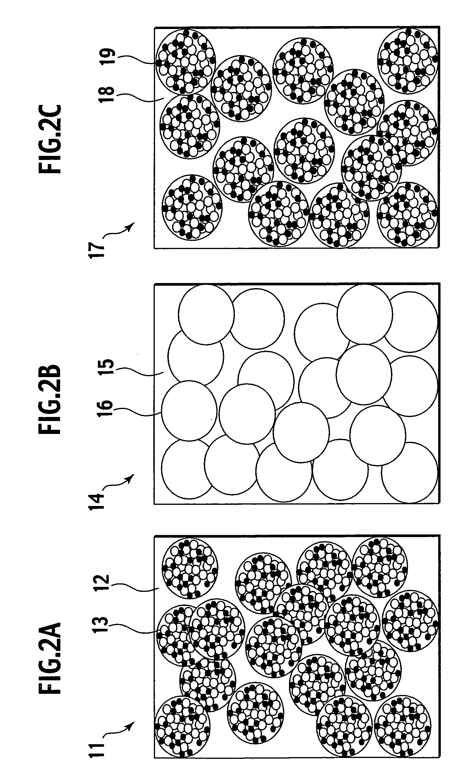
[0294] A positive electrode active material containing 7 g of spinel manganese with a mean particle diameter of 1 μm, conductive material containing 2 g of carbon powder (Denka Black manufactured by DENKI KAGAKU KOGYO KABUSHIKI KAISYA) with a mean particle diameter of 30 nm, polymer electrolyte containing 4 g of polyethylene oxide with a molecular weight of approximately 2000, electrolyte salt containing 2 g of LiBETI and a solvent containing 20 g of acetonitrile were weighed and mixed using a mixer, thereby obtaining positive electrode ink. A viscosity of the resulting positive electrode ink was 5000 cP.

[0295] (2) Preparation of Negative Electrode Ink (Step (2) of the First Embodiment)

[0296] A negative electrode active material containing 9 g of graphite with a mean particle diameter of 1 μm, polymer electrolyte containing 4 g of polyethylene oxide with a molecular weight of approximately 2000, el...

example 2

[0319] (1) Preparation of Positive Electrode Ink (Steps (1)+(3) of the Second Embodiment)

[0320] A positive electrode active material containing 7 g of spinel manganese with a mean particle diameter of 1 μm, conductive material containing 2 g of Denka Black with a mean particle diameter of 30 nm, polymer electrolyte containing 4 g of polyethylene oxide with a molecular weight of approximately 2000, electrolyte salt containing 2 g of LiBETI and a solvent containing 85 g of acetonitrile were weighed and mixed using a mixer, thereby preparing a mixture slurry. A viscosity of the resulting mixture slurry was 100 cP.

[0321] The mixture slurry prepared as described above was granulated into particles with a mean diameter of 10 μm using a spray drier. The prepared positive electrode polymer particles were dispersed in carbon tetrachloride, thereby preparing positive electrode ink. A viscosity of the resulting positive electrode particle ink was 5000 cP.

[0322] (2) Preparation of Negative E...


PUM


Abstract

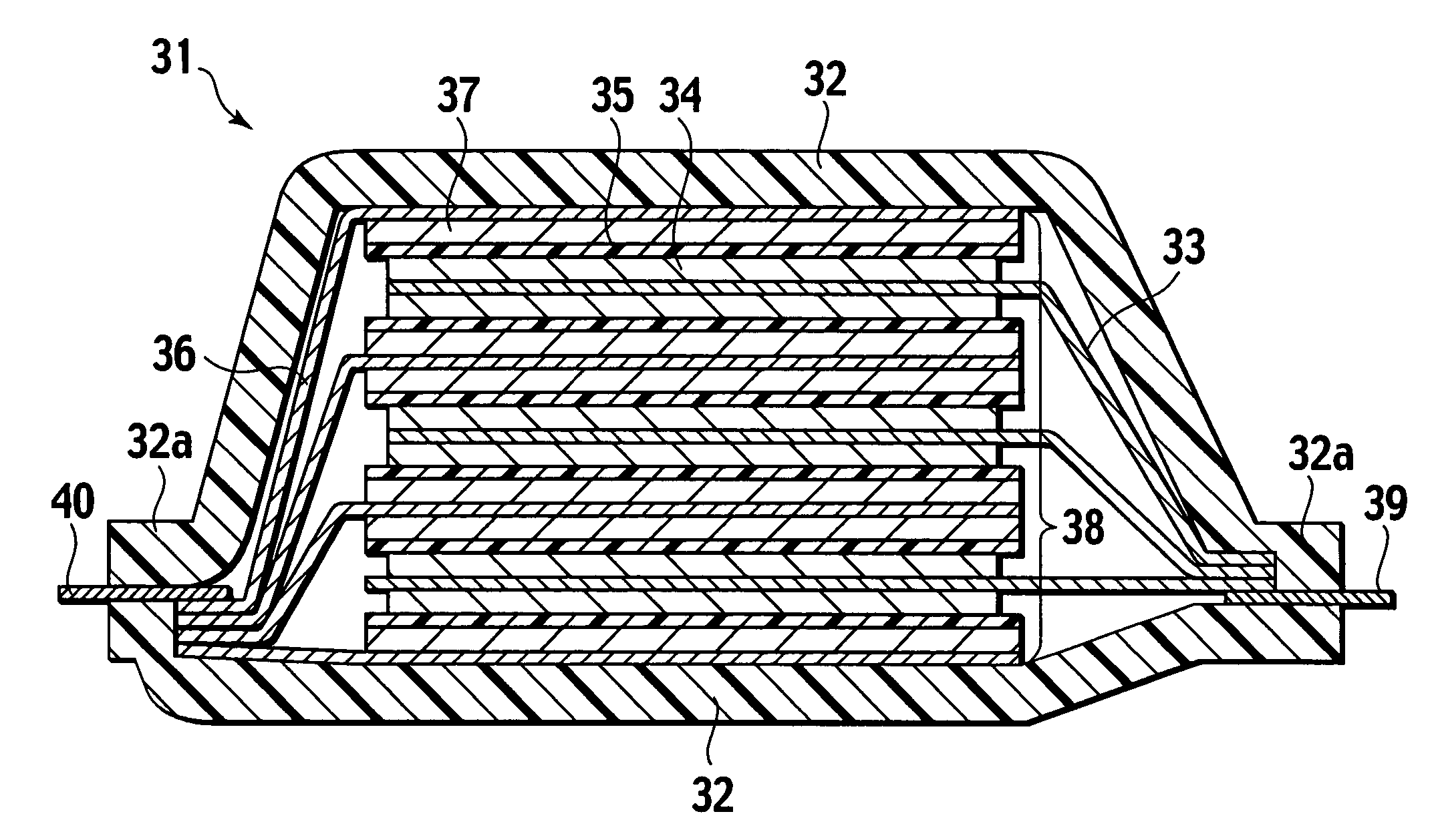
A method of manufacturing a solid electrolyte battery includes a step of thermally pressing a composite layer including a positive electrode ink layer, an electrolyte ink layer and a negative electrode ink layer that are formed by coating a positive electrode ink, an electrolyte ink and a negative electrode ink. Further, the positive electrode ink, the electrolyte ink and the negative electrode ink contain a polymer electrolyte. By this method, it is possible to improve the flow of ions across respective interlayers of a positive electrode active material layer, a solid electrolyte layer and a negative electrode active material layer.

Description

BACKGROUND OF THE INVENTION [0001] 1. Field of the Invention [0002] The present invention relates to a method of manufacturing a solid electrolyte battery and a solid electrolyte battery obtained by such a method. [0003] 2. Description of the Related Art [0004] In recent years, research and development work has been undertaken to provide a motor drive power supply and an auxiliary power supply for a hybrid use in order to promote an electric vehicle (EV), a hybrid electric vehicle (HEV) and a fuel cell vehicle (FCV) against the background with an increasing concern for environmental protection movements. In such applications, a lithium ion secondary battery, which is able to perform charging and discharging on repeated cycles, has been used. [0005] In applications needed for a high power output and high energy density to drive motors for EV, HEV and FCV, a single large size battery cannot be manufactured, as a matter of practice, and it has been a general practice to use an assemble...

Claims


Application Information

Patent Timeline
IPC IPC(8): H01M4/04H01M4/36H01M10/05H01M10/0565H01M10/0585H01M10/38
CPCH01M4/0404H01M4/0416Y10T29/49115H01M10/0565H01M10/38H01M4/043Y02E60/10Y02P70/50
Inventor SAITO, TAKAMITSUHORIE, HIDEAKI
Owner NISSAN MOTOR CO LTD
Learn More