
Method, device and computer program for designing a circuit having electric wires and optical connections

a technology of optical connections and circuits, applied in the direction of cad circuit design, optical elements, instruments, etc., can solve the problems of circuits that need further improvement in terms of high speed operation and circuit size, circuits that have electrical wire delays, etc., to achieve high reliability, short period of time, and high-efficiency optoelectronics

Inactive Publication Date: 2005-06-16
CANON KK
View PDF20 Cites 31 Cited by
  • Summary
  • Abstract
  • Description
  • Claims
  • Application Information

AI Technical Summary

Benefits of technology

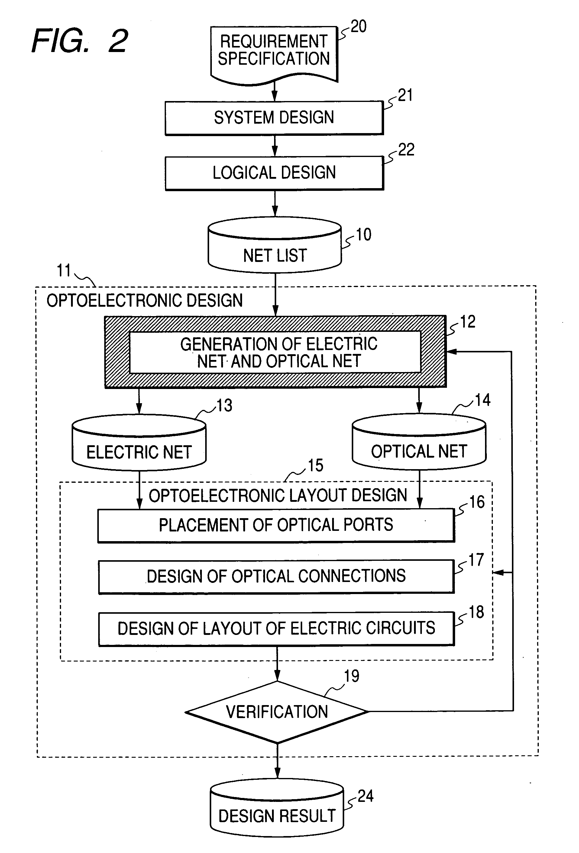
[0010] Preferably, a fifth step of placing optical ports that are parts having a photoelectric conversion feature is provided after said second step and before said third and fourth steps. Thus, it is possible to optimize the optoelectronic circuit as a whole in addition to optimally designing optical circuits and electronic circuits by carrying out a place and route design with priority for optical ports that operate as interfaces of optical circuits and electronic circuits.
[0012] Preferably, said optoelectronic circuit has a package structure including a plurality of semiconductor chips, an electric wiring layer and an optical connection layer and at least part of the interconnections of the semiconductor chips is realized optically by way of the optical connection layer. With such an arrangement, said optical connection layer may have two-dimensional optical waveguides and optical ports for inputting optical signals from and outputting optical signals to the two-dimensional optical waveguides so that it is possible to optically interconnect combinations of any of the optical ports. Preferably, said semiconductor chips have reconfigurable circuits so that it is possible to alter the internal configurations of the semiconductor chips and additionally alter the optical connections among the semiconductor chips by way of said optical connection layer.
[0017] In view of the above-identified problems, an optoelectronic circuit designed according to the invention has a plurality of electronic circuits, a plurality of electric wiring sections and a plurality of optical connecting sections to show a configuration that can be designed by a design method as defined above or designed by a design method according to the invention. In other words, such an optoelectronic circuit allows a design method according to the invention to be conducted reliably.
[0032] Thus, a design method and a design device according to the invention can fully exploit the potentials of hardware and design an optimum optoelectronic circuit highly reliably in a short period of time. Since a design method according to the invention integrally combines an operation of designing electronic circuits and that of designing optical circuits, electronic circuits and optical circuits are designed in a coordinated manner and hence a highly optimized optoelectronic circuit is designed as a whole. As a result, it is possible to ultimately provide a high cost performance effect for the designed optoelectronic circuit. Additionally, a design method according to the invention can be applied to an operation of automatically designing a reconfigurable optoelectronic circuit.
[0033] Particularly, it is possible to realize an optoelectronic circuit in which optical circuits and electronic circuits are designed in a highly coordinated manner by generating electric nets and optical nets so as to minimize the number of electric nets in the second step and placing optical ports so as to minimize the total length of electric wires in the third step.

Problems solved by technology

However, as the processing speed rises, problems arise to the circuits thereof, including wiring delays, EMI (electromagnetic interference) noises and so on.
However, such circuits need further improvements in terms of high speed operation and circuit size.
However, with such a design technique of designing optical circuits and electronic circuits separately, it is difficult to fully exploit the potentials of the circuits (hardware) of the two categories.
To be more accurately, while optical circuits and electronic circuits may be designed optimally, the design of the optoelectronic circuit for integrally combining them is not optimal.
Additionally, designing an optoelectronic circuit requires advanced professional knowledge of circuits of the two categories, a vast amount of time and huge cost.

Method used


Image

  • Method, device and computer program for designing a circuit having electric wires and optical connections
  • Method, device and computer program for designing a circuit having electric wires and optical connections
  • Method, device and computer program for designing a circuit having electric wires and optical connections

Examples


example 1

[0121] In this example, a reconfigurable optoelectronic circuit is used as hardware and the above-described optoelectronic layout technique is applied to the automatic design of the circuit. The reconfigurable optoelectronic circuit as used herein is a circuit where reconfigurable electronic circuits (FPGAs) 107 as shown in FIG. 5A and flexible optical circuits using planar or two-dimensional (2D) optical waveguides (sheet-shaped optical transmission mediums) 101, which will be described in greater detail hereinafter, coexist as mixture.

[0122] Reconfigurable electronic circuits including FPGAs tend to require longer time and higher cost for optimizing the design as a result of the efforts for raising the scale and the degree of integration because of the increased influence of electric wiring delay that come to intervene. On the other hand, systems that need to be reconfigurable on a real time basis are required to be designed in a short period of time. Additionally, while techniqu...

example 2

[0181] In this example, a circuit having ASICs (custom chips) along with FPGAs and memories for hardware is designed. As in the case of Example 1, the basic structure of the optoelectronic circuit of this example is illustrated in FIG. 6. A major restriction of this example is to use custom chips. Other restrictions for the hardware include that the maximum number of FPGA chips is four (4), that of electric wiring layers is ten (10) while the number of optical connection layers is one (1) and that of optical ports is sixteen (16).

[0182] The difference of scope of design between Example 2 and Example 1 will be described below.

[0183] While the details of the insides of the FPGAs and the optical module are variable in Example 1, the placement of the chips and the optical ports is fixed. More specifically, a predefined reconfigurable system which is an optoelectronic circuit comprising nine FPGAs and nine optical ports is optimally designed in Example 1. Additionally, the positions of...

example 3

[0197] Hardware of the type illustrated in FIGS. 9A and 9B is used in Example 3. Referring to FIGS. 9A and 9B, there are shown a substrate 100, an optical transmission medium 101, optical ports 102, light 103 being transmitted, an electric wiring layer 105 and semiconductor chips 107 (107a through 107d) (while electric wiring layer 105 contains electric wires, they are not shown). In FIGS. 9A and 9B reference symbols 107a, 107b, 107c denote FPGAs and reference symbol 107d denotes a custom chip. FIG. 9A is a plan view and FIG. 9B is a cross sectional view that corresponds to FIG. 9A.

[0198] In this example, the optical module having an optical transmission medium 101 and optical ports 102 is arranged in an area of a part of the substrate and semiconductor chips 107 are arranged in the remaining area. As restriction, the optical module is handled as part and no semiconductor chip can be arranged there. Since an electric wiring layer is provided separately, electric wires can be arrang...


PUM


Abstract

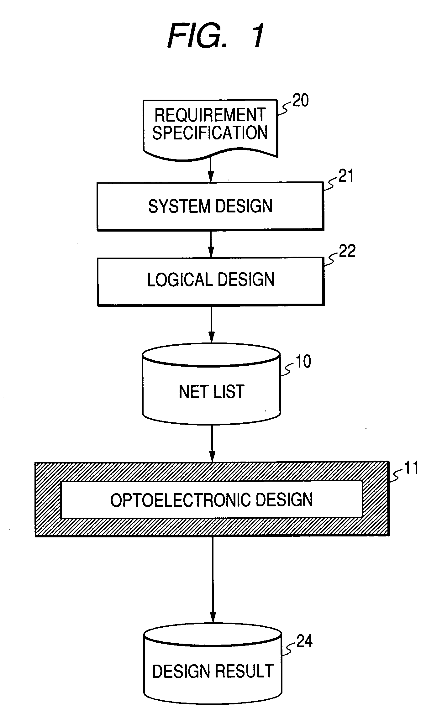
A design method and a design device can design an optimal optoelectronic circuit in a relatively short period of time by exploiting the performance of hardware. They have a step of generating a connection list to be carried by electric circuits (electric nets) and a connection list to be carried by optical connections (optical nets), a step of designing the layout of electric circuits and subsequently designing optical connections and a step of evaluating the designs.

Description

BACKGROUND OF THE INVENTION [0001] 1. Field of the Invention [0002] This invention relates to a method, a device and a computer program for designing a circuit having both electronic circuits connected by electric wires and optical circuits using optical connections as integral components thereof (to be also referred to as optoelectronic circuit). [0003] 2. Related Background Art [0004] Recently, information processing devices including personal computers, mobile phones and personal digital assistants (PDAs) have been required to operate at high processing speed in addition to be compact and lightweight. However, as the processing speed rises, problems arise to the circuits thereof, including wiring delays, EMI (electromagnetic interference) noises and so on. Techniques have been proposed to utilize optical circuits using optical connections in order to avoid wiring delays, EMI noises and other problems (see, inter alia, Japanese Patent Application Laid-Open No. H6-308519). [0005] M...

Claims


Application Information

Patent Timeline
Patent Type & Authority Applications(United States)
IPC IPC(8): G02B6/12G02B6/43G06F17/50
CPCG06F17/5045G02B6/43G06F30/30H01L2224/16225H01L2924/15192
Inventor IWASAKI, TATSUYA
Owner CANON KK
Learn More