
Bullet with booster filling and its manufacture

a technology of booster filling and bullets, applied in the field of bullets, can solve the problems of small increase in velocity, severe distortion of high-speed bullets fired into liquids like water or living tissue, and ineffective increase of penetration, so as to prevent the hollow point of a bullet and increase the expansion of the bull

Inactive Publication Date: 2005-06-16
LAMM CHARLES ROBERT EMILE
View PDF27 Cites 32 Cited by
  • Summary
  • Abstract
  • Description
  • Claims
  • Application Information

AI Technical Summary

Benefits of technology

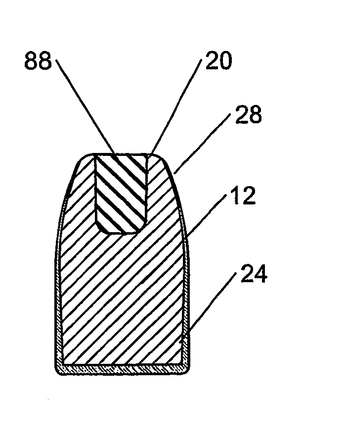
[0046] The embodiments of the invention disclosed herein achieve one or more of the following purposes: improving, hastening and assuring bullet expansion during the penetration of liquid targets; preventing the hollow point of a bullet from clogging with debris from intermediate targets; increasing bullet expansion during the perforation of hard materials; preventing the expansion of training bullets during the penetration of liquid targets; and allowing users to identify different cartridge designs that would otherwise have an identical external appearance. Another purpose is to provide a technique for designing bullets that achieve these ends.
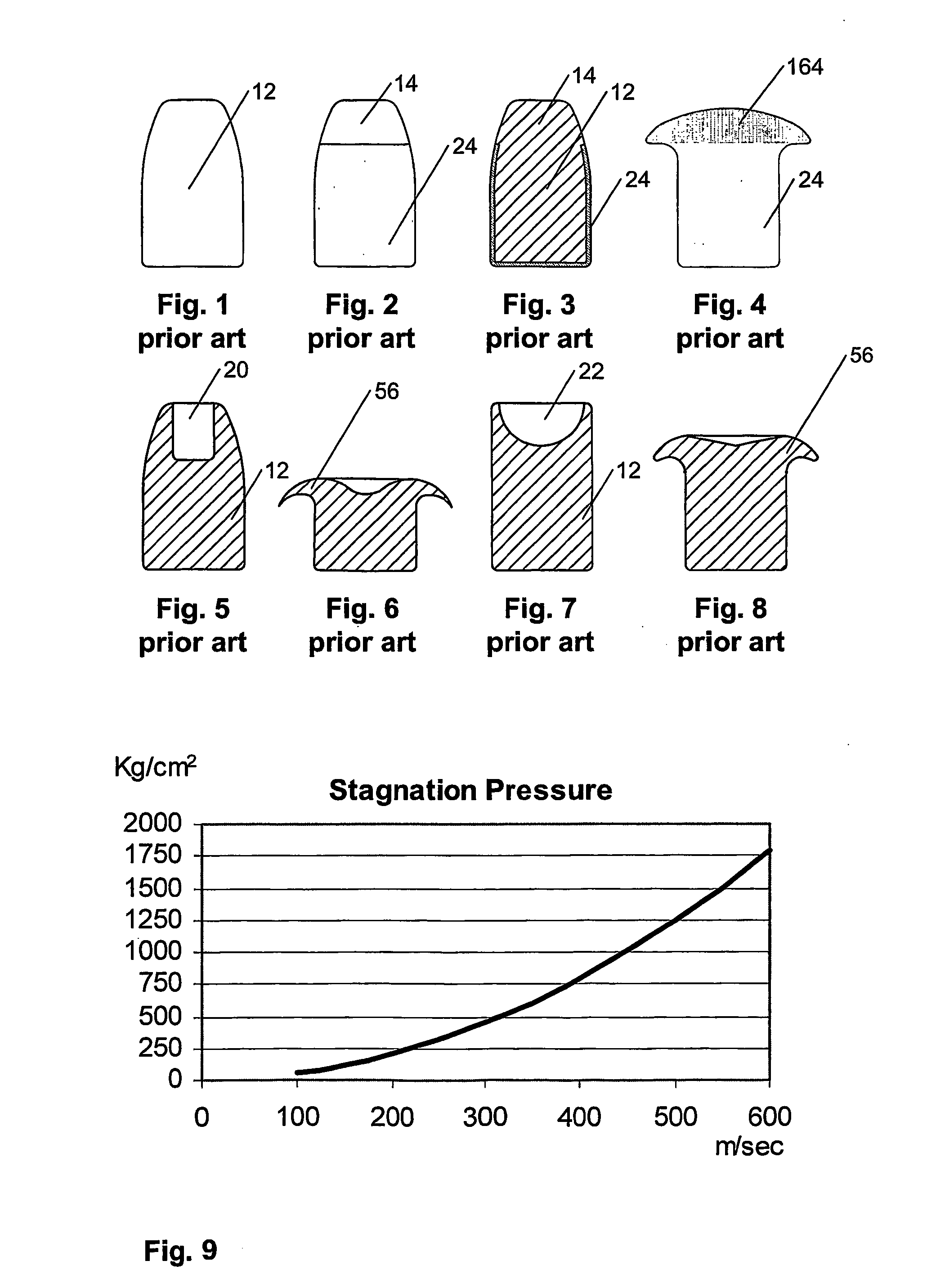
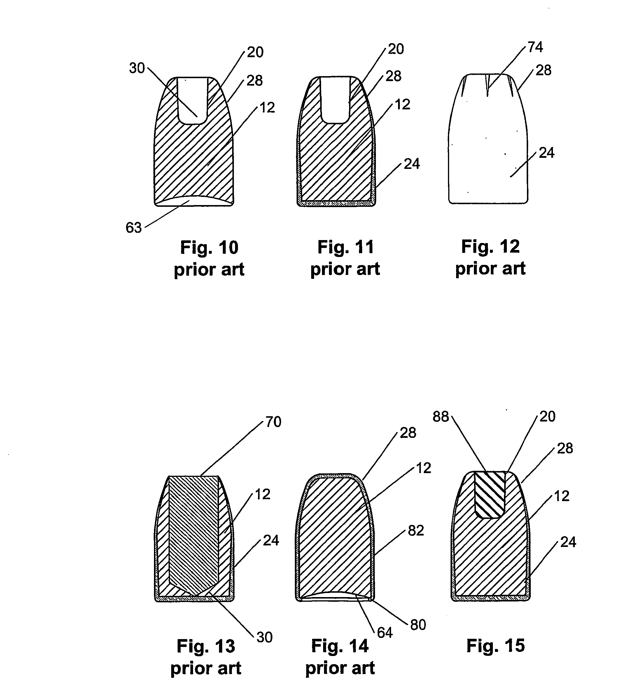
[0048] Preferably, the filling is an elastomer that transmits the pressure (e.g., stagnation pressure) applied to the open forward end of the cavity in the bullet (e.g., when the bullet strikes a liquid target or a simulated tissue) to the interior surface of the cavity. The invention is advantageous because it can be employed in all existing hollow point bullets, regardless of the cavity shape, whether the bullet is jacketed or not. Hollow point bullets fitted with the filling of the invention disclosed herein are unaffected by the penetration of intermediate barriers that would otherwise fill the hollow point cavity with debris, thus impeding the bullet's expansion. Moreover, thin metal plate penetration can be reduced by combining the approach of filling the cavity with an appropriate elastomer with modification of other ammunition features, such as bullet shape and velocity. The invention provides much better performance than similar ammunition, in terms of cost, stopping power, penetration depth and metal plate perforation performance.

Problems solved by technology

High velocity bullets fired into liquids like water or living tissue are severely distorted.
In that penetration in liquids is a logarithmic function of velocity, small increases in velocity (from 350 to 410 m / sec) do not effectively increase penetration.
Velocities as high as this are very difficult to achieve in calibres other than magnums.
Intermediates barriers such as wood, textiles, leather or gypsum, are easily perforated by hand gun bullets, as their thickness and resistance are low.
However, hollow points are easily filled by the barrier's material.
Stopping power is reduced and penetration in liquid targets or tissue simulants increase to unacceptable values.
Metal plates offer a different kind of problem to hollow point bullets.
All the former designs are hollow point bullets that expand while penetrating liquid targets but none comply with the following requirements: preventing the hollow point of a bullet from clogging with debris from intermediate targets; increasing expansion during the perforation of hard materials; preventing the expansion of training bullets during the penetration of liquid targets; and allowing users to identify different cartridge designs that would otherwise have an identical external appearance.
Notwith-standing these characteristics, it cannot be employed to produce a non-expanding hollow point bullet for training purposes nor does it allow for identification of different cartridge types.
Moreover, none of the references and no combination of the references teach how to effectively manufacture an elastomer-filled hollow point bullet or a rigid polymer-filled hollow point bullet.

Method used


Image

  • Bullet with booster filling and its manufacture
  • Bullet with booster filling and its manufacture
  • Bullet with booster filling and its manufacture

Examples


working examples

[0227] Two prototype ammunition designs were developed and tested to illustrate the possibilities of basing a new bullet design on the invention disclosed herein.

[0228] One is low penetration ammunition. For home defense, ammunition that is issued to personnel with little training in defense or that is employed in crowded areas should be convenient to use and have the following features: good stopping power, i.e., stopping power equivalent to a military (e.g., NATO) ammunition would be the minimum acceptable; low penetration of intermediate barriers, i.e., although police require high penetration of cars in defensive applications, not only would this feature be unnecessary but it may be a handicap in crowded areas or in home defense applications; and low report, i.e., a loud report like that of a 9 mm NATO round may produce permanent hearing damage, while a report that is three decibels (dB) less would make the report acceptable.

[0229] The second is ammunition for police applicati...

working example no.1

Working Example No. 1

[0230] Thin metal plate penetration increases with the square power of velocity and decreases with the bullet's frontal surface area. If the only desired feature of a bullet is a low thin metal plate penetration, bullet velocity can be reduced as necessary by reducing the powder load. Automatic pistol ammunition must produce sufficient recoil to operate the slide. Recoil is a linear function of bullet mass and velocity. The maximum bullet mass is limited by the cartridge design. Bullets have a maximum possible length (and mass) limited by the cartridge dimensions, as the assembly cannot exceed a certain length. Comparing FIG. 39 with FIG. 40, it is noticeable in FIG. 39 that the bullet is longer (and heavier) and consequently smaller powder space 102 left in the case bellow the bullet is restricted. A ten percent increment in the bullet's mass would reduce the powder capacity by 50 percent, reducing the kinetic energy by the same amount, and the bullet would not...

working example no.2

Working Example No. 2

[0236] Referring to FIG. 40, another cartridge as a preferred embodiment of the invention is illustrated. In this embodiment, the cartridge comprised powder filling space 100 and second prototype bullet 160 having cavity filled with elastomer 42, both of which were situated in case 97. Second prototype bullet 160 was comprised of a plain lead alloy with six percent antimony and had a weight of 7.5 grams. Because no jacket was provided, embodiments of second prototype bullet 160 were either copper clad or Teflon® coated. The hollow point had a cavity that was 3.75 in diameter by 9.5 mm in length and contained elastomer filling 42 in accordance with the invention disclosed herein.

[0237] Upon striking a liquid target at a velocity of 350 m / sec, bullet 160 expanded to sixteen mm, compared to a 12 mm expansion for a Silver Tip® bullet, producing a pressure wave intensity that was 40 percent higher. In that the expanded ring disintegrated after reaching maximum expan...


PUM


Abstract

A bullet having a cavity in its forward end that is open at that end and a filling situated within said cavity. Preferably, the filling comprises an elastomer. Preferably, the elastomer filling is vulcanized. More preferably, the vulcanized elastomer filling has a Shore hardness in the range from about 6 to about 90. Alternatively, the filling is a colored rigid polymer filling, if a non-expanding training hollow point bullet is desired. In particular, the invention is a filling and its application to hollow point bullets for the purposes of: improving bullet expansion during the penetration of liquid targets; preventing clogging with debris from intermediate targets; increasing expansion during the perforation of hard materials; preventing the expansion of training bullets; and allowing users to identify different cartridge designs. The invention is also devices and methods for introducing the filling into the cavity.

Description

[0001] This application claims the benefit of U.S. Provisional Application No. 60 / 367,843 filed on Mar. 25, 2002 and U.S. Provisional Application No. 60 / 432,492 filed on and Dec. 10, 2002; the disclosures of which applications are incorporated by reference as if fully set forth herein.TECHNICAL FIELD [0002] This invention relates to improvements to bullets having an open, forward end cavity, including hollow point bullets. In particular, the invention relates to a filling to be applied to the cavity of a hollow point bullet for the purpose of improving, hastening and assuring its expansion and other purposes and to devices and methods for introducing the filling into the cavity. BACKGROUND ART [0003] In this document, these terms are defined as follows: [0004] TARGET: The desired place of impact of a bullet. [0005] LIQUID TARGET: A target that behaves like a liquid having a density of 1.0, such as 10 percent gelatin or human soft tissues. [0006] INTERMEDIATE BARRIERS: Materials inte...

Claims


Application Information

Patent Timeline
Patent Type & Authority Applications(United States)
IPC IPC(8): F42B8/12F42B12/34F42B12/74
CPCF42B8/12F42B12/745F42B12/34
Inventor LAMM, CHARLES ROBERT EMILE
Owner LAMM CHARLES ROBERT EMILE
Learn More