Display unit
a display device and display technology, applied in the field of display devices, can solve the problems of large drive power, large mass, slow response, etc., and achieve the effects of high reliability, low power consumption, and high brightness display devices
- Summary
- Abstract
- Description
- Claims
- Application Information
AI Technical Summary
Benefits of technology
Problems solved by technology
Method used
Image
Examples
embodiment 1
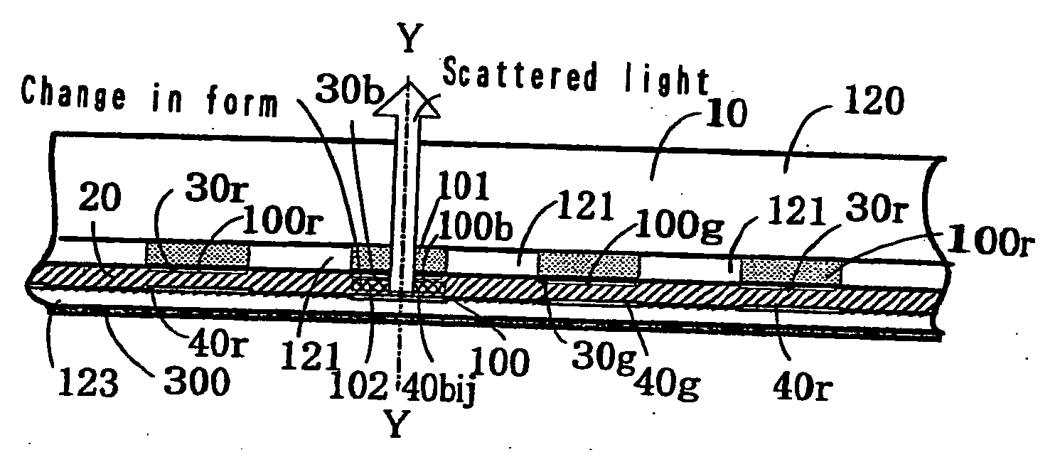
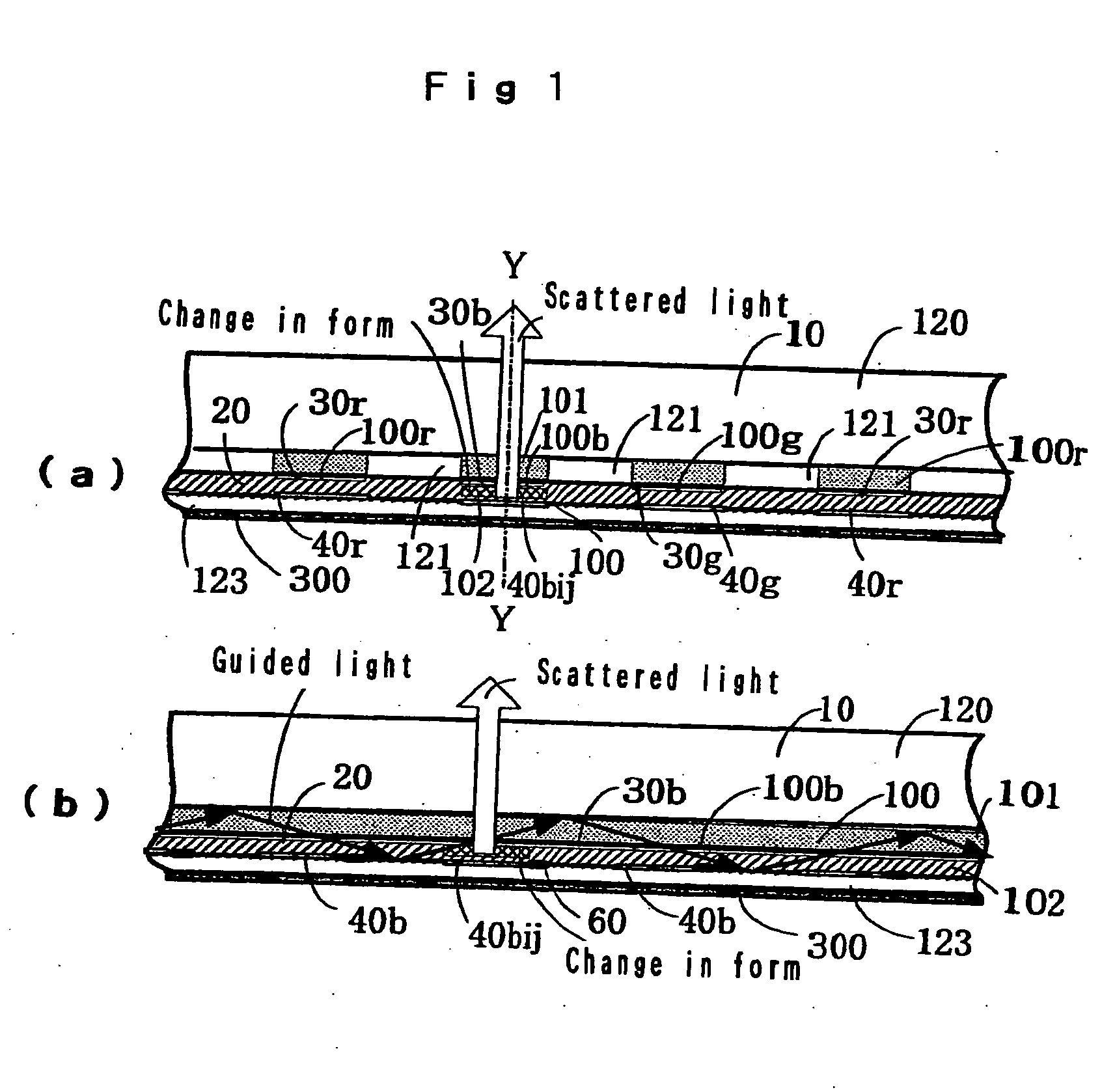
[0059]FIG. 1 illustrates an embodiment of the component of the display device of this invention using dynamic scattering liquid crystal as the electroresponsive material 20, and transparent plate 10 as the clad portion 120 of the optical waveguide 100 comprising the pair of the first optical waveguide 101 and the second optical waveguide 102. The component also uses the plate 10 as the supporting board for the thin optical waveguide 100. In addition, the three primary colors, optical waveguide for the color red 100r, optical waveguide for the color green 100g, and optical waveguide for the color blue 100b, are arrayed sequentially on both sides of the transparent clad portion 121, so that the device is capable of full-color display.
[0060]FIG. 1 also illustrates how the electroresponsive material 20 becomes murky and causes the blue light, or the guided light, to be emitted outside the transparent plate 10 and observed as a blue pixel. The electroresponsive material 20 comprises the...
embodiment 2
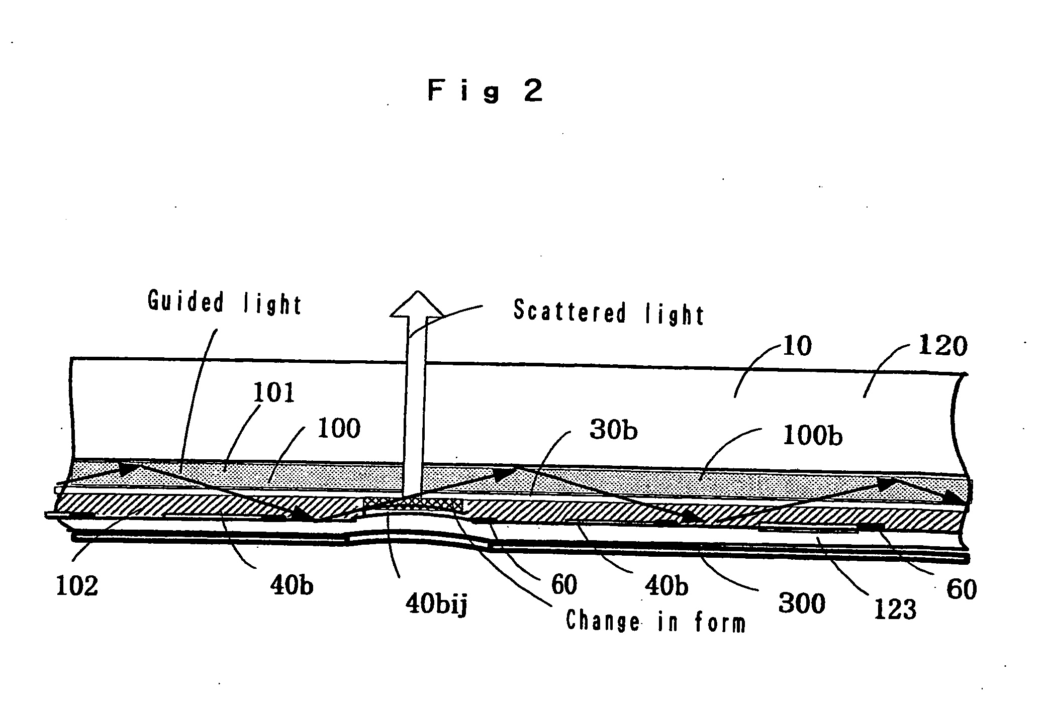
[0066]FIG. 2 shows the longitudinal sectional views along the optical waveguide 100b for the color blue, using a jelly-like gel (electroresponsive gel) that expands and shrinks under an electric field as the electroresponsive material 20 for the display device of this invention, as is shown in FIG. 1(b). When a color image signal voltage is applied between the transparent electrode 30b and the electrode 40ij selected from the electrode 40, paired to the electrode 30b, the electroresponsive gel that will become the second optical waveguide 102 changes in form (shrinks), decreasing its sectional area. Thus, the blue light guided there is scattered and emitted outside the transparent plate 10. Gel used as artificial muscle is suitable for the electroresponsive gel. Transparent polyurethane gel, for example, can also be used. Epoxy sheet or polyethylene sheet of about 50 É m thickness that deforms easily according to the expansion and shrinkage of the gel can be used as the clad portion...
embodiment 3
[0067] Differing from FIG. 1 in Embodiment 1, FIG. 3 shows the horizontal sectional views of an embodiment in which only several optical waveguides 100r for the color red and 100b for the color blue are formed sandwiching the clad portions 121 on the same plane of the plate 10, while the optical waveguide 100g for the color green is formed periodically on the clad portion 123 sandwiched by the clad portion 122. Each optical waveguide 100g for the color green is located between the optical waveguides 100r for the color red and 100b for the color blue. Also in FIG. 3, the image signal voltage over the threshold limit value is applied to the pair electrodes comprising the transparent electrode 30b and the electrode 40b ij formed on the optical waveguide 100b for the color blue. The electric field thus caused makes the electroresponsive material 20 (Light-scattering liquid crystal layer of the second optical waveguide 102) murky and emits the scattered light to the outside as pixels fro...
PUM
| Property | Measurement | Unit |
|---|---|---|
| voltage | aaaaa | aaaaa |
| refractive index | aaaaa | aaaaa |
| transparent | aaaaa | aaaaa |
Abstract
Description
Claims
Application Information
 - Generate Ideas
- Intellectual Property
- Life Sciences
- Materials
- Tech Scout
- Unparalleled Data Quality
- Higher Quality Content
- 60% Fewer Hallucinations
Browse by: Latest US Patents, China's latest patents, Technical Efficacy Thesaurus, Application Domain, Technology Topic, Popular Technical Reports.
© 2025 PatSnap. All rights reserved.Legal|Privacy policy|Modern Slavery Act Transparency Statement|Sitemap|About US| Contact US: help@patsnap.com


