Light emitting assembly with heat dissipating support

a technology of light emitting assembly and support, which is applied in the direction of discharge tube/lamp details, non-printed electric components association of printed circuits, non-metallic protective coating applications, etc., can solve the problem of high cost of thin film techniques, and achieve the effect of low cost, high heat dissipation capacity, and structural strength

Inactive Publication Date: 2005-06-09
INT RESISTIVE OF TEXAS
View PDF22 Cites 113 Cited by
  • Summary
  • Abstract
  • Description
  • Claims
  • Application Information

AI Technical Summary

Benefits of technology

[0006] In this invention, a light emitting assembly includes a substrate or heat sink, a series of circuit traces on the substrate and one or more light emitting elements. The substrate or heat sink is a metal which is coated with a thin electrically insulating layer. Preferably, the metal is anodized to produce the electrically insulating layer. The metal may be of any suitable type but preferably is an anodizable type such as aluminum, magnesium and their alloys. The substrate is anodized in a conventional manner to produce a thin, tough electrically insulating coating bonded directly to the underlying metal. Anodized aluminum substrates have three powerful advantages: low cost, structural strength and high heat dissipating capacity. In some situations, the substrate is masked to provide sections with no anodized layer to provide a direct thermal path from the LED to the substrate. In addition, masked sections of the substrate may be used to reflect light from the LED's thereby increasing the amount of light emitting from the assembly and reducing the amount of energy absorbed by the substrate.

Problems solved by technology

Thin film techniques are more expensive but are capable of producing devices capable of operating at higher voltages because the electrically insulating layer is not degraded by the heat processes needed in the manufacture of thick film devices.

Method used


Image

  • Light emitting assembly with heat dissipating support
  • Light emitting assembly with heat dissipating support
  • Light emitting assembly with heat dissipating support

Examples


Embodiment Construction

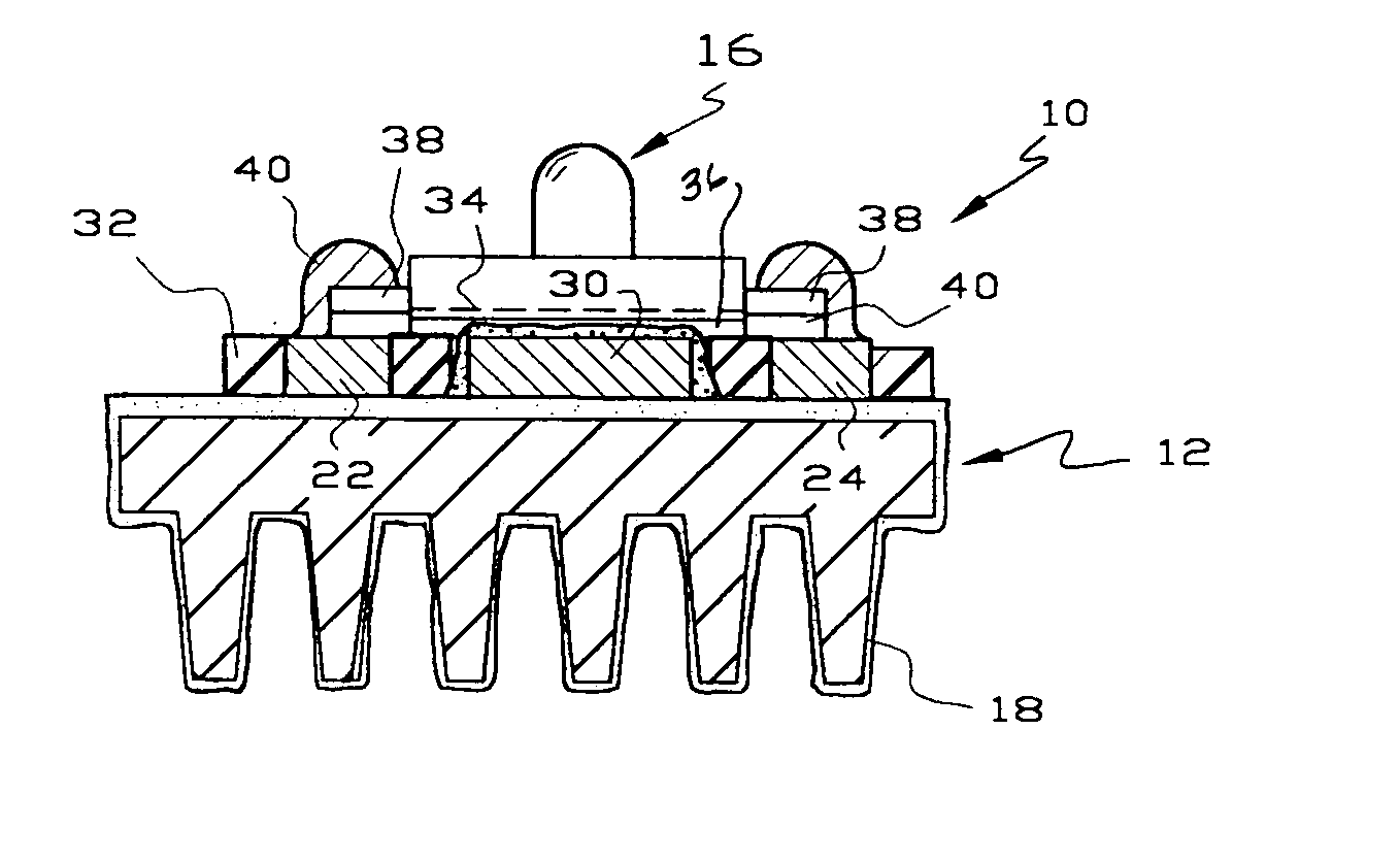
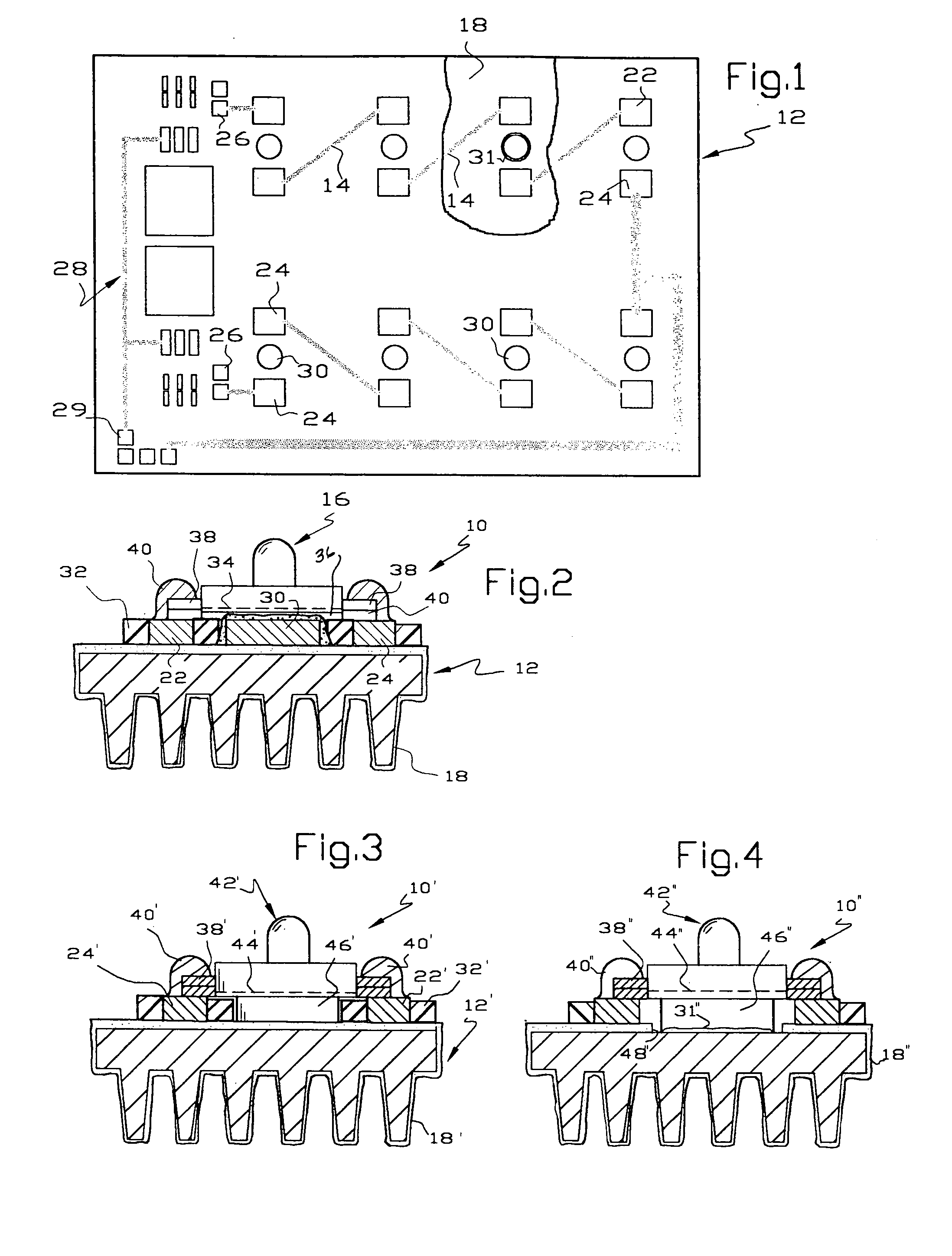
[0023] Referring to FIGS. 1-2, there is illustrated a light emitting assembly 10 of this invention comprising, as major components, a metal substrate or heat sink 12, a series of circuit traces 14 on the substrate and a series of light emitting elements or LED's 16. The assembly 10 may be used to provide a light source for a variety of applications, such as a vehicle headlight, taillight, brake light, or non-vehicle light source in which a series of LED's are used to deliver light.

[0024] The substrate or heat sink 12 may by of any suitable metal that has appropriate heat dissipating characteristics, strength, cost and the ability to receive a thin electrically insulating layer or coating 18. Preferred metals include aluminum, aluminum alloys, magnesium, magnesium alloys, zinc, pot metal and the like. The electrically insulating coating 18 is formed with a thickness of ten microns to one thousand microns, preferably on the order of about fifty to one hundred microns. The electricall...


PUM


Abstract

A light emitting assembly includes a metal substrate for dissipating heat from the assembly. The metal substrate includes an electrically insulating layer or coating on at least one side. Circuit traces are applied to the electrically insulating layer using either thick or thin film techniques. At least the ends of the circuit traces include a metallic section to which leads of light emitting elements are soldered or wire-bonded. A metallic section is provided adjacent the light emitting element to transfer heat to the underlying substrate and/or to reflect light from the element away from the substrate. A clear finish retards tarnishing of the reflecting metallic section.

Description

[0001] This invention relates to an improved light emitting assembly having a heat dissipating support for reducing the operating temperature of the assembly. BACKGROUND OF THE INVENTION [0002] Light sources are evolving toward assemblies of light emitting elements such as light emitting diodes which are known in the art as LED'S. Assemblies of LED's are being used or will be used in many high volume applications because they produce substantial light in proportion to the power consumed, are long lived and are extremely reliable. One such application is light sources for vehicles, such as headlights, taillights and directional signal lights. Other applications include replacements for florescent and incandescent lights and the like. [0003] High output LED's, particularly when a large number are used on a common support, have a problem because they produce a significant amount of heat and the current generation of LED's begin to lose brightness when they are hotter than about 100° C....

Claims


Application Information

Patent Timeline
Patent Type & Authority Applications(United States)
IPC IPC(8): F21K99/00F21S8/00F21S8/10F21V29/00F21Y101/02H05K1/02H05K1/05H05K1/09H05K1/18H05K3/28
CPCF21K9/00F21V29/763F21S48/215F21S48/328F21V29/004F21W2111/00F21Y2101/02H05K1/0204H05K1/021H05K1/0274H05K1/053H05K1/092H05K1/182H05K3/28H05K2201/09781H05K2201/10106H05K2201/10969H05K2201/2054F21S48/10F21Y2115/10F21S41/141F21S43/14F21S45/47F21V29/89F21S41/153
Inventor MORRIS, THOMAS M.
Owner INT RESISTIVE OF TEXAS
Why Eureka
Try Eureka