
Method for repairing components using environmental bond coatings and resultant repaired components

a technology of environmental bond coating and component, applied in the field of components, can solve the problems of component loss of critical dimension, growth of environmental coating, and special requirements, and achieve the effects of reducing thickness, extending component life, and increasing repairability

Active Publication Date: 2005-05-19
GENERAL ELECTRIC CO
View PDF39 Cites 14 Cited by
  • Summary
  • Abstract
  • Description
  • Claims
  • Application Information

AI Technical Summary

Benefits of technology

[0008] According to an embodiment of the invention, a repaired component is disclosed. The repaired component comprises an engine run component having a base metal substrate, a portion of the base metal substrate between about 1-3 mils in thickness and an overlying bond coat having been removed to create a remaining base metal substrate of reduced thickness. The repaired component further comprises a lower growth environmental bond coating comprising an alloy having an aluminum content of about 10-60 atomic percent applied to the remaining base metal substrate so that upon subsequent repair of the component, less than about 1-3 mils in thickness of the remaining base metal substrate is removed because of less environmental coating growth into the substrate than the prior bond coat. Advantageously, the repaired component has extended component life and increased repairability.
[0009] According to another embodiment of the invention, a method for repairing a coated component, which has been exposed to engine operation, is disclosed. The method comprises providing an engine run component including a base metal substrate having thereon a bond coat; and removing the bond coat. A portion of the base metal substrate between about 1-3 mils in thickness also is removed to create a remaining base metal substrate of reduced thickness. The method further comprises applying a lower growth environmental bond coating to the remaining base metal substrate comprising an alloy having an aluminum content of about 10-60 atomic percent so that upon subsequent repair of the component, less than about 1-3 mils in thickness of the remaining base metal substrate is removed because of less environmental coating growth into the substrate than the prior bond coat. Advantageously, the method extends component life and increases repairability of the component.
[0010] According to a further embodiment of the invention, a repaired component is disclosed comprising an engine run component having a base metal substrate, a portion of an overlying bond coat on the substrate having been removed. The component further comprises a lower growth environmental bond coating comprising an alloy having an aluminum content of about 10-60 atomic percent applied to the substrate so that upon subsequent repair of the component, less than about 1-3 mils in thickness of the base metal substrate is removed because of less environmental coating growth into the substrate than the prior bond coat. Advantageously, the repaired component has extended component life and increased repairability.
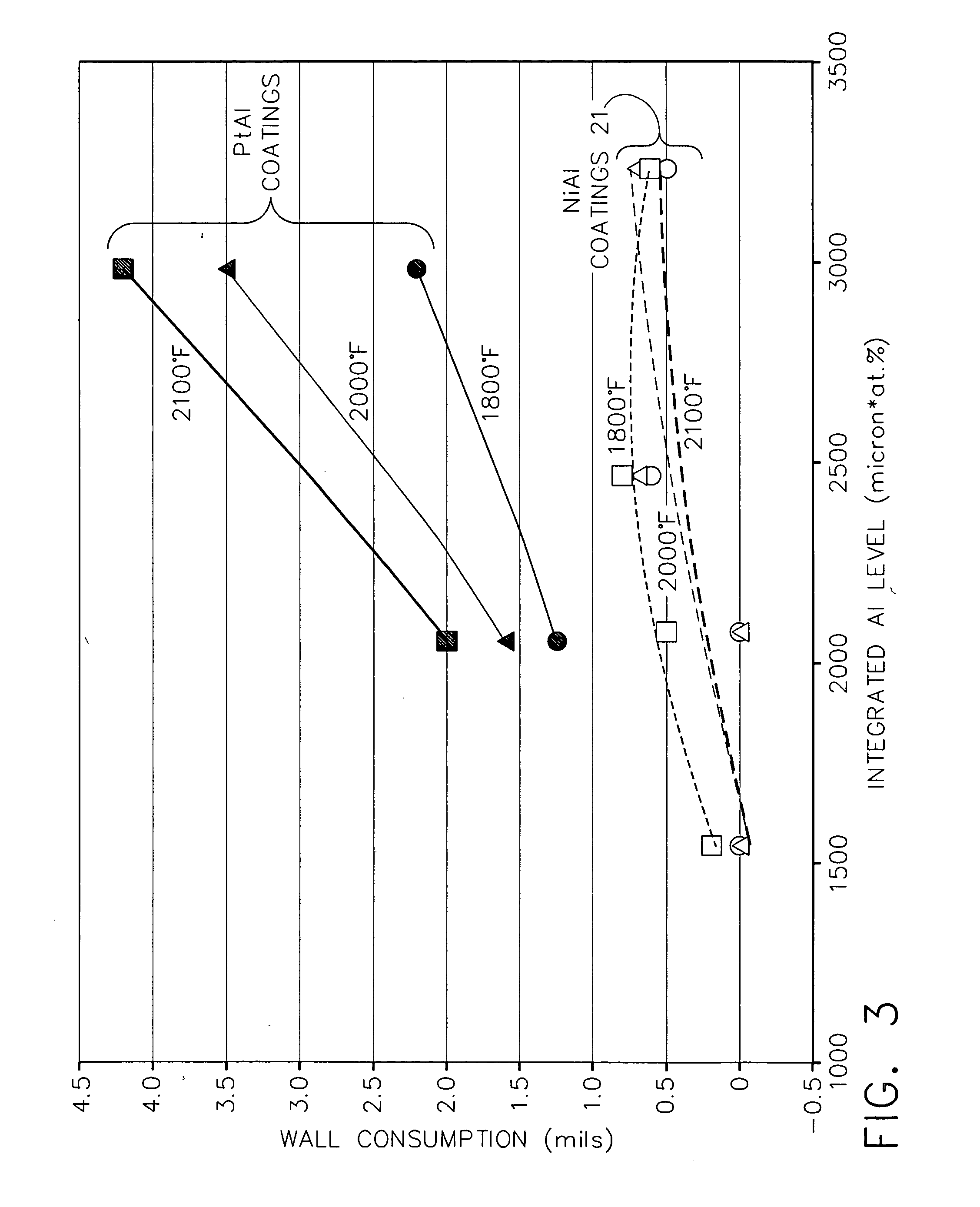
[0011] In accordance with a further embodiment of the invention, a repaired gas turbine engine component is disclosed comprising an engine run gas turbine engine component having a base metal substrate, a portion of the base metal substrate between about 1-3 mils in thickness and an overlying bond coat having been removed to create a remaining base metal substrate of reduced thickness. The component further comprises a lower growth environmental bond coating comprising an alloy having an aluminum content of about 10-60 atomic percent applied to the remaining base metal substrate so that upon subsequent repair of the component, less than about 1-3 mils in thickness of the remaining base metal substrate is removed because of less environmental coating growth into the substrate than the prior bond coat. Also, thickness of the environmental bond coating is controlled to produce an integrated aluminum level of less than or equal to about 4000 μm*at. % Al, and wherein the environmental bond coating comprises a β-NiAl overlay coating. Advantageously, the repaired component has extended component life and increasing repairability Other features and advantages will be apparent from the following more detailed description, taken in conjunction with the accompanying drawings, which illustrate by way of example the principles of the invention.

Problems solved by technology

The latter requirement is particularly demanding due to the different coefficients of thermal expansion between thermal barrier coating materials and superalloys typically used to form turbine engine components.
For instance, removal may be necessitated by erosion or impact damage to the ceramic layer during engine operation, thermal spallation of the TBC or by a requirement to repair certain features such as the tip length of a turbine blade.
During engine operation, the components may experience loss of critical dimension due to squealer tip loss, TBC spallation and oxidation / corrosion degradation.
The high temperature operation also may lead to growth of the environmental coatings.
Current state-of-the art repair methods often result in removal of the entire TBC system, i.e., both the ceramic layer and bond coat.
One such method is to use abrasives in procedures such as grit blasting, vapor honing and glass bead peening, each of which is a slow, labor-intensive process that erodes the ceramic layer and bond coat, as well as the substrate surface beneath the coating.
Although stripping is effective, this process also may remove a portion of the base substrate thereby thinning the exterior wall of the part.
When design is limited to particular minimum airfoil dimensions, multiple repairs of such components may not be possible.

Method used


Image

  • Method for repairing components using environmental bond coatings and resultant repaired components
  • Method for repairing components using environmental bond coatings and resultant repaired components
  • Method for repairing components using environmental bond coatings and resultant repaired components

Examples


Embodiment Construction

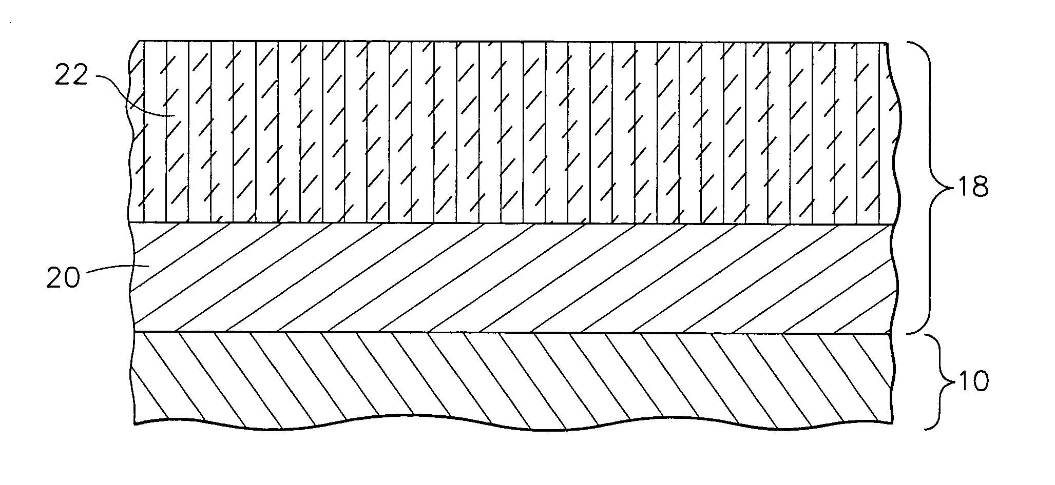
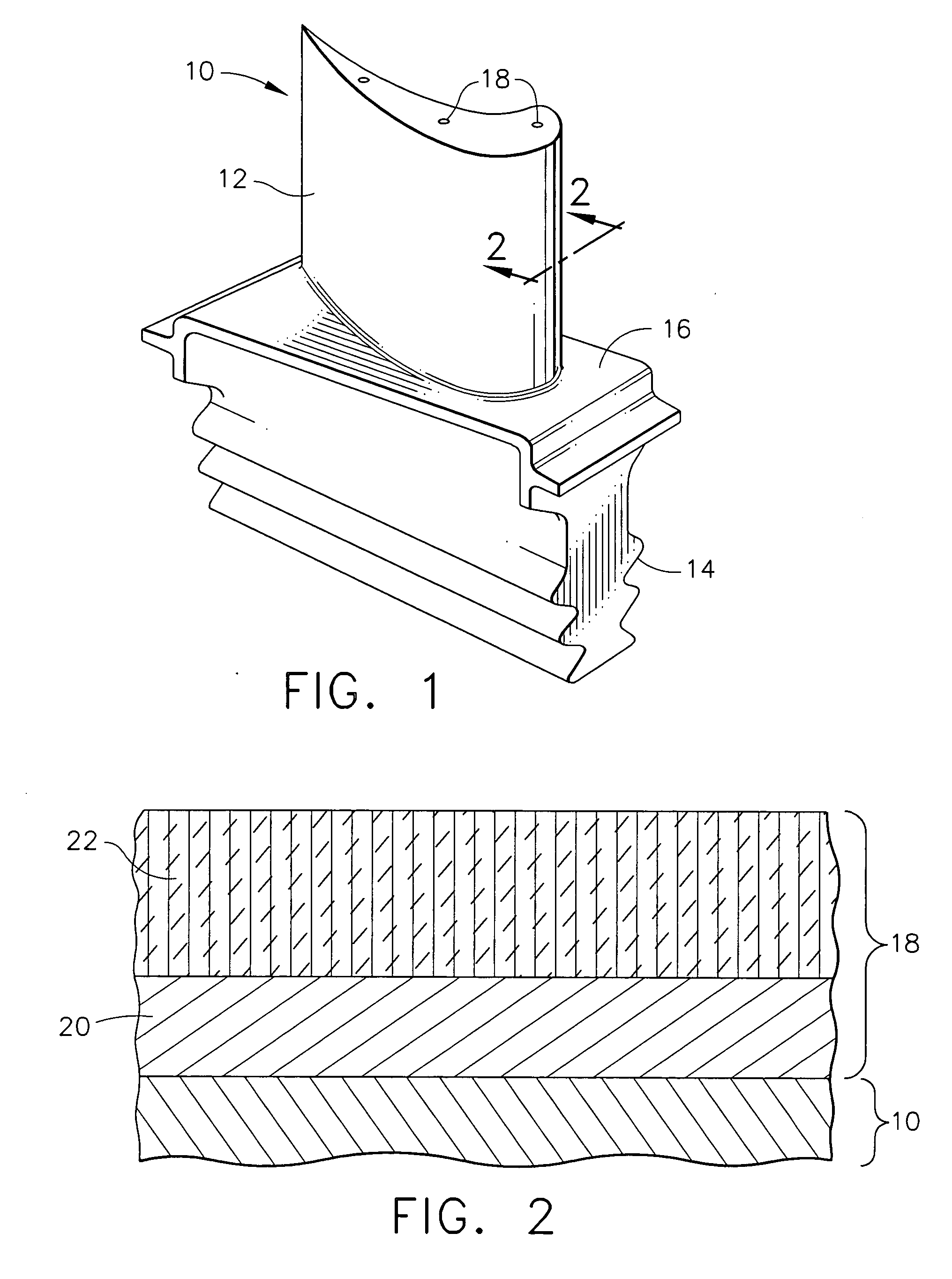
[0015] The repair method of the present invention is generally applicable to components that operate within environments characterized by relatively high temperatures, and are therefore subjected to severe thermal stresses and thermal cycling. Notable examples of such components include the high and low pressure turbine nozzles and blades, shrouds, combustor liners and augmentor hardware of gas turbine engines. Other examples include airfoils, in general, and static parts such as vanes. One particular example is the high pressure turbine blade 10 shown in FIG. 1. For convenience, the method of the present invention will be described in the context of repairing blade 10. However, one skilled in the art will recognize that the method described below may be readily adapted to repairing any other gas turbine engine part coated with an environmental bond coat, with or without an overlying ceramic layer 22. Accordingly, as used herein, bond coat or environmental bond coat does not require...


PUM

PropertyMeasurementUnit
thicknessaaaaaaaaaa
thicknessaaaaaaaaaa
thicknessaaaaaaaaaa

Abstract

According to an embodiment of the invention, a repaired component is disclosed. The repaired component comprises an engine run component having a base metal substrate, a portion of the base metal substrate between about 1-3 mils in thickness and an overlying bond coat having been removed to create a remaining base metal substrate of reduced thickness. The repaired component further comprises a lower growth environmental bond coating comprising an alloy having an aluminum content of about 10-60 atomic percent applied to the remaining base metal substrate so that upon subsequent repair of the component, less than about 1-3 mils in thickness of the remaining base metal substrate is removed because of less environmental coating growth into the substrate than the prior bond coat. Advantageously, the repaired component has extended component life and increased repairability.

Description

[0001] Diffusion coatings, such as aluminides and platinum aluminides applied by chemical vapor deposition processes, and overlay coatings such as MCrAlY alloys, where M is iron, cobalt and / or nickel, have been employed as environmental coatings for gas turbine engine components. [0002] Ceramic materials, such as zirconia (ZrO2) partially or fully stabilized by yttria (Y2O3), magnesia (MgO) or other oxides, are widely used as the topcoat of TBC systems, when a topcoat is employed. The ceramic layer is typically deposited by air plasma spraying (APS) or a physical vapor deposition (PVD) technique. TBC employed in the highest temperature regions of gas turbine engines is typically deposited by electron beam physical vapor deposition (EB-PVD) techniques. [0003] To be effective, the TBC topcoat must have low thermal conductivity, strongly adhere to the article and remain adherent throughout many heating and cooling cycles. The latter requirement is particularly demanding due to the diff...

Claims


Application Information

Patent Timeline
Patent Type & Authority Applications(United States)
IPC IPC(8): C23C4/02C23C4/08B23P6/00C23C10/02C23C10/08C23C10/28C23C10/48C23C14/16C23C16/20C23C18/54C23C28/00C23C28/04C23C30/00C23F1/00C25D3/50C25D7/00C25D7/04F01D5/28F01D25/00F02C7/00
CPCC23C10/02C23C18/54C23C28/321C23C28/325C23C28/3455C25D7/04Y10T428/12944C23C28/345Y10T428/12937Y10T428/12736Y10T428/265Y10T428/12771Y10T428/1259C23C28/3215
Inventor RIGNEY, JOSEPH D.DAROLIA, RAMGOPAL
Owner GENERAL ELECTRIC CO
Learn More