
Lithium/air batteries with LiPON as separator and protective barrier and method

Inactive Publication Date: 2005-05-05
CYMBET CORP
View PDF62 Cites 143 Cited by
  • Summary
  • Abstract
  • Description
  • Claims
  • Application Information

AI Technical Summary

Benefits of technology

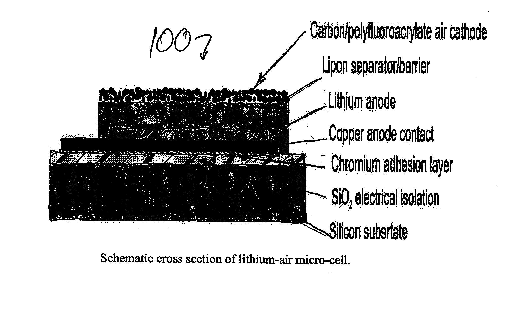
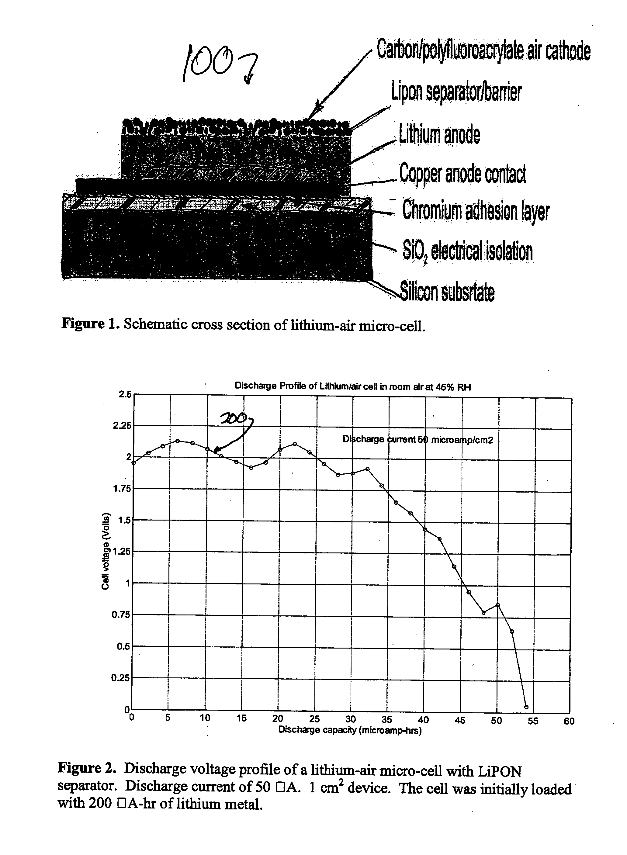
[0024] In their work, Abraham and Jiang made a preliminary estimate of shelf-life, or self discharge, of the lithium / air, organic electrolyte battery by storing a cell in flowing O2 for 5 days and comparing its discharge capacity to a freshly made cell. The stored cell delivered ˜95% of the capacity of a fresh cell when discharged under similar conditions. The authors discussed the need to protect the lithium anode from oxygen and moisture in order to extend shelf-life. A method of providing protection for the lithium anode from oxygen and moisture can be achieved by using LiPON as the separator in lithium-air cells. LiPON functions in the dual role as separator and as a barrier preventing oxygen and moisture from reaching the lithium metal anode while still allowing lithium ion transport from the lithium metal anode to the air cathode.
[0057] Some embodiments provide a vacuum deposited solid state, inorganic air cathode. In some embodiments, the air cathode needs to be both electrically conducting and provide good transport to lithium ions. In some embodiments, the structure must be porous to oxygen and have sufficient surface area for the deposition of the lithium oxide products. In some embodiments, such a material is created from the codeposition of carbon and the LiPON separator material. Carbon provides electrical conductivity and nucleation sites for lithium oxide deposition. LiPON would provide an ionic conductive path for lithium. In some embodiments, the entire structure is made porous on a submicron scale by adjusting the deposition conditions. For example, the vacuum deposition technique of glancing angle deposition (GLAD) (See,for example, K. Robbie, C. Shafai, and M.J. Brett, “Thin Films with Nanometer Scale Pillar Microstructures”, Journal of Materials Research 14, 3158-3163 (1999) and J. C. Sit, D. Vick, K. Robbie, and M. J. Brett, “Thin Film Microstructural Control Using Glancing Angle Deposition by Sputtering”, Journal of Materials Research 14, 1197-1199 (1999). ) allows highly structured, intricate columns of material to be made on the sub-micron scale,

Problems solved by technology

One drawback to portable devices is the need to include the power supply with the device.
Sufficient battery capacity can result in a power supply that is quite heavy or large compared to the rest of the device.
Another drawback of conventional batteries is the fact that some are fabricated from potentially toxic materials that may leak and be subject to governmental regulation.

Method used


Image

  • Lithium/air batteries with LiPON as separator and protective barrier and method
  • Lithium/air batteries with LiPON as separator and protective barrier and method
  • Lithium/air batteries with LiPON as separator and protective barrier and method

Examples


Embodiment Construction

[0010] In the following detailed description of the preferred embodiments, reference is made to the accompanying drawings that form a part hereof, and in which are shown by way of illustration specific embodiments in which the invention may be practiced. It is understood that other embodiments may be utilized and structural changes may be made without departing from the scope of the present invention.

[0011] The leading digit(s) of reference numbers appearing in the Figures generally corresponds to the Figure number in which that component is first introduced, such that the same reference number is used throughout to refer to an identical component which appears in multiple Figures. The same reference number or label may refer to signals and connections, and the actual meaning will be clear from its use in the context of the description.

Terminology

[0012] In this description, the term metal applies both to substantially pure single metallic elements and to alloys or combinations o...


PUM

PropertyMeasurementUnit
Electric potential / voltageaaaaaaaaaa

Abstract

A method and apparatus for making lithium / air batteries with LiPON as separator and protective barrier, and the resulting cell(s) and / or battery(s). Some embodiments include an apparatus that includes a lithium anode; a polymer-air cathode; and a LiPON separator between the anode and cathode. In some embodiments, the polymer-air cathode includes a carbon-polyfluoroacrylate material. In some embodiments, the anode overlays a copper anode contact.

Description

CROSS-REFERENCES TO RELATED INVENTIONS [0001] This invention is related to the following: U.S. patent application Ser. No. 09 / 816,602 entitled “Device Enclosures with Integrated Batteries” filed Mar. 23, 2001, U.S. patent application Ser. No. 09 / 815, entitled “Battery-Operated Wireless-Communication Apparatus and Method,” filed Mar. 23, 2001, and U.S. patent application Ser. No. 09 / 336,620 entitled “Solid State Activity-Activated Battery Device and Method” filed on Jan. 2, 2003, and U.S. patent application Ser. No. 09 / 336,621 entitled “APPARATUS AND METHOD FOR DEPOSITING MATERIAL ONTO MULTIPLE INDEPENDENTLY MOVING SUBSTRATES IN A CHAMBER” filed on Jan. 2, 2003, and U.S. patent application Ser. No. 09 / 336,619 entitled “APPARATUS AND METHOD FOR DEPOSITING MATERIAL ONTO MULTIPLE INDEPENDENTLY MOVING WEBS,” filed on Jan. 2, 2003; and U.S. patent application Ser. No. 09 / 336,662 entitled “ACTIVE WIRELESS TAGGING SYSTEM ON PEEL AND STICK SUBSTRATE” filed on Jan. 2, 2003, each of which is i...

Claims


Application Information

Patent Timeline
IPC IPC(8): B05D5/12H01M4/66H01M4/86H01M4/96H01M6/40H01M12/06H01M50/431
CPCH01M2/1646H01M4/661H01M4/96Y10T29/49115H01M12/06Y02E60/50H01M6/40H01M50/431
Inventor KLAASSEN, JODY J.
Owner CYMBET CORP
Learn More