Eureka AIR delivers breakthrough ideas for toughest innovation challenges, trusted by R&D personnel around the world.

Bag-in-container with prepressurized space between inner bag and outer container

a bag-in-container and prepressurized technology, applied in rigid containers, pliable tubular containers, transportation and packaging, etc., can solve the problems of uncontrollable bag collapse, inability to connect to a source of pressurized gas, and inability to control the collapse of the bag, so as to prolong the shelf life of the fluid

Inactive Publication Date: 2011-10-13
ANHEUSER BUSCH INBEV SA
View PDF11 Cites 134 Cited by
  • Summary
  • Abstract
  • Description
  • Claims
  • Application Information

AI Technical Summary

Benefits of technology

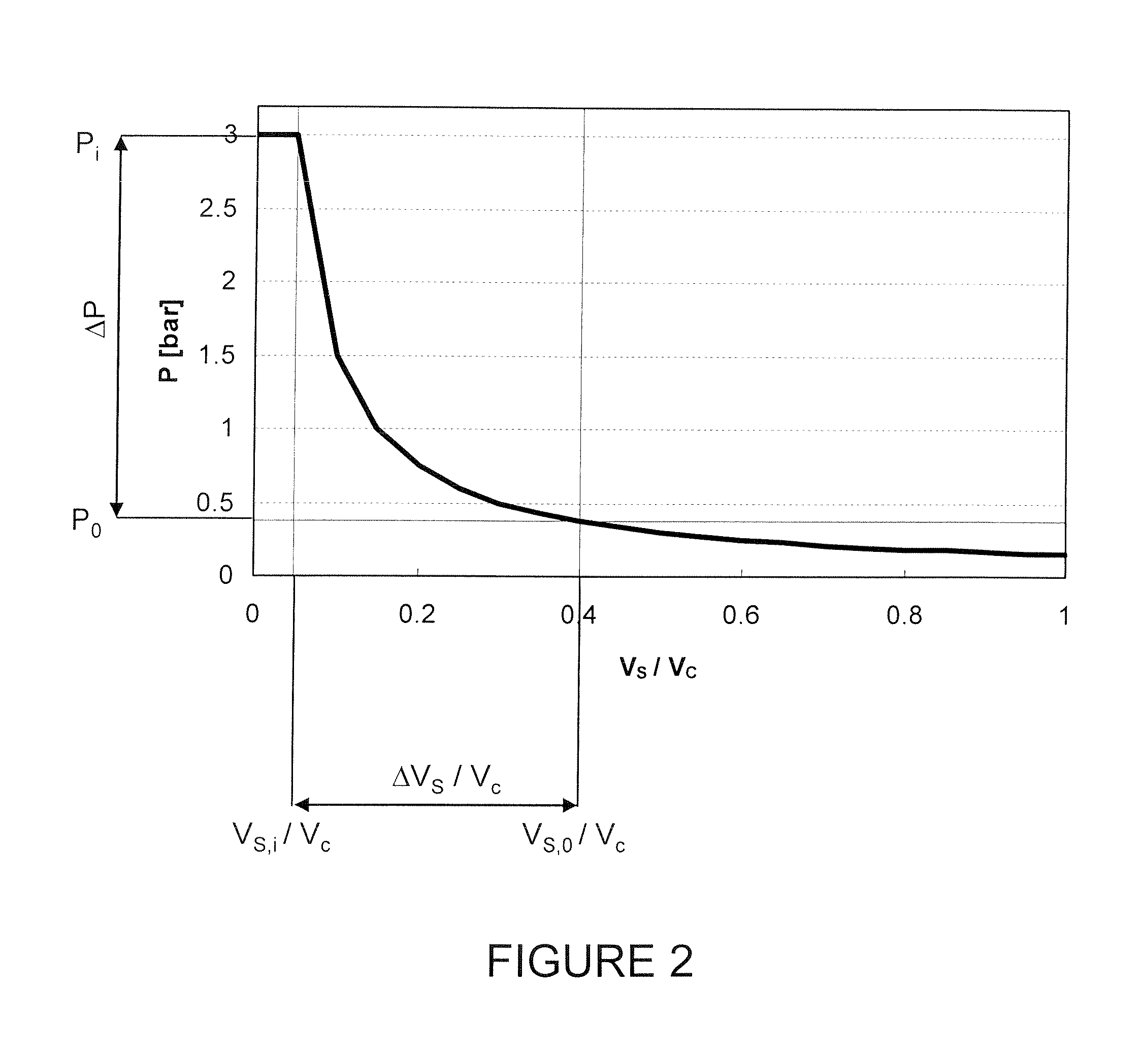
The present invention relates to bag-in-containers for dispensing fluids, which comprise an inner layer forming a bag filled with fluid, a separatable outer layer, and a mouth fluidly connecting the bag to the atmosphere. The container also has at least one space vent fluidly connecting the space between the inner and outer layers to the atmosphere. The invention provides a solution for dispensing techniques involving injection of a pressurized gas through the vents to drive the liquid out of the bag. The invention also includes a kit of parts comprising the bag-in-container and an appliance to accommodate it, and a method for controlling the gas flow between the space and the atmosphere. The gas stored in the space between the inner bag and outer container is at an initial pressure (Pi) and the space is pre-pressurized with gas to ensure smooth functioning of the bag-in-container. The invention can be used in various applications, such as dispensing therapeutic fluids and beverages. The pre-pressurization with a gas like CO2 or N2 can also prolong the shelf life of the fluid by forming a blanket or barrier to oxygen diffusion.

Problems solved by technology

They can also be used in techniques where the liquid is sucked out of the bag in order to balance the pressure in the space with the atmosphere as the bag volume decreases, but said vents are simple holes and comprise no closing means and cannot be connected to a source of pressurized gas.
The layer separation, however, is not always as reproducible as could be expected, which could lead to uncontrolled bag collapse and to the formation of pockets full of fluid sealed from the mouth of the bag, and thus to the incomplete dispensing of the fluid.

Method used


Image

  • Bag-in-container with prepressurized space between inner bag and outer container
  • Bag-in-container with prepressurized space between inner bag and outer container
  • Bag-in-container with prepressurized space between inner bag and outer container

Examples


Embodiment Construction

The Bag-In-Container

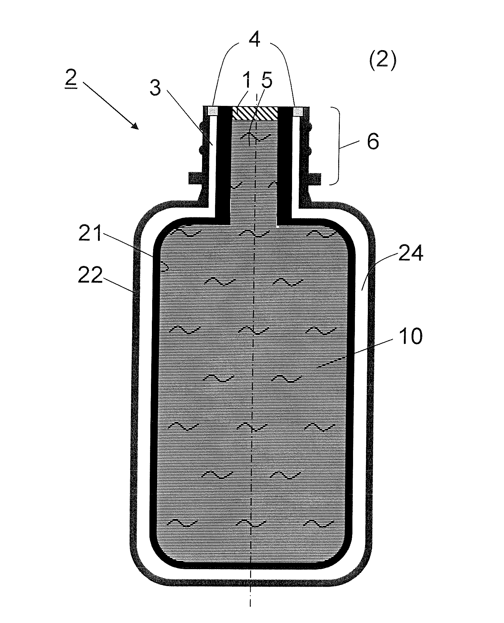
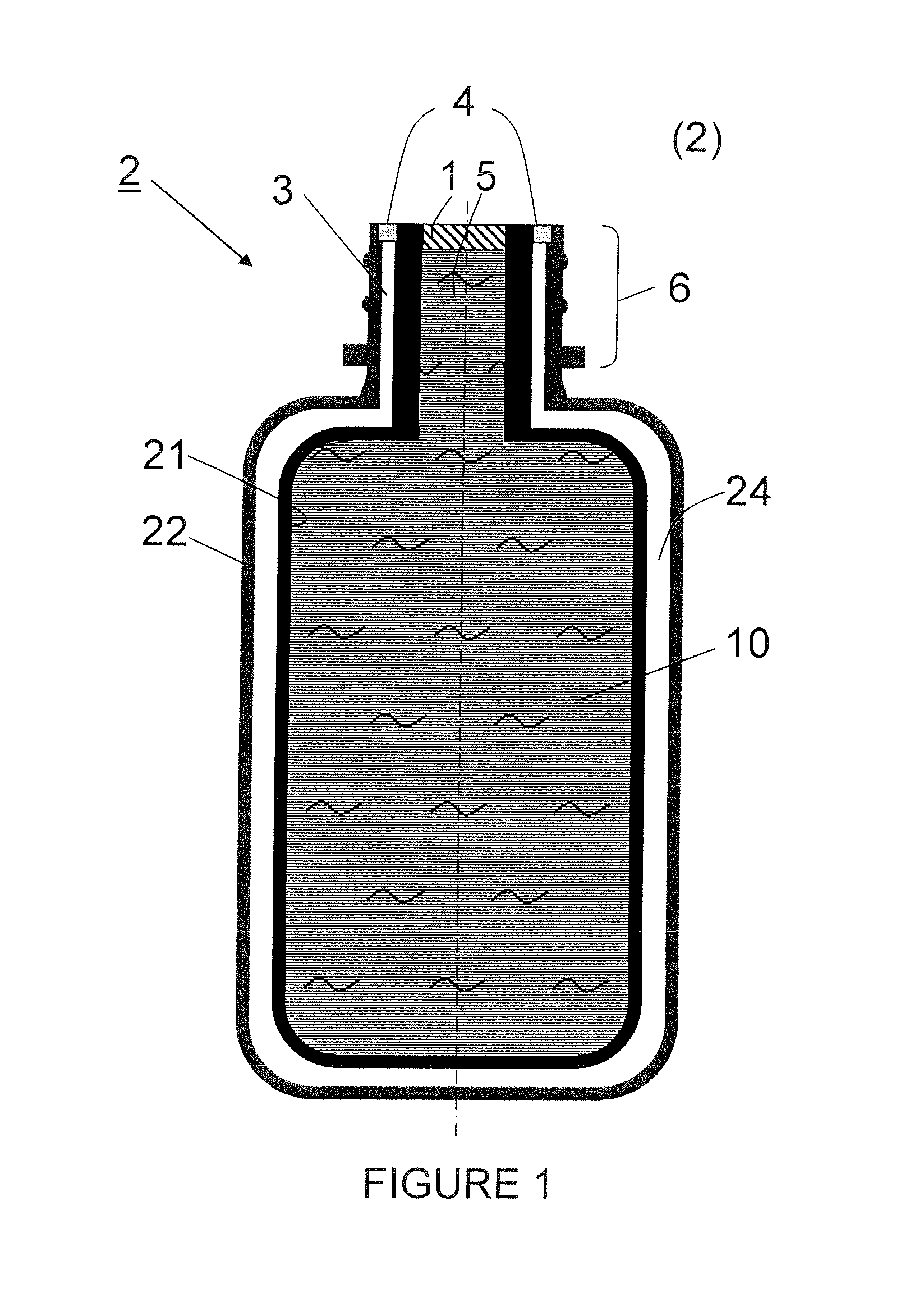
[0030]Referring now to appended FIG. 1, there is illustrated a bag-in-container (2) comprising an inner bag (21) filled with a fluid (10) and an outer container (22) joined at least at the level of the neck region (6) by an interface (not shown in the Figure). The space (24) of volume (VS,i) between the inner bag and outer container (21) and (22) is in fluid communication with at least one vent (3) and is filled with a certain amount of pre-pressurizing gas at a pressure (Pi) stored in the initial space volume (VS,i) which will be defined below. Said vent is separated from the atmosphere by closing means (4) suitable for controlling the gas flow across the vent (3). A closing means is herein considered as controlling the flow across vent (3) if it can alternate at least once from a closed position preventing any gas flow, to an open position allowing gas flow across vent (3). A simple stopper or cap usually found in pressurized bag-in-containers is not considered...


PUM


Abstract

Bag-in-container having an inner layer forming a bag filled with a fluid, the bag being separatable from an outer layer forming the container. The bag-in-container has a mouth fluidly connecting the volume defined by the bag to the atmosphere and separated therefrom by a seal. The container further having at least one space vent fluidly connecting the space between inner and outer layers and to the atmosphere. A vent provides a closure to control the gas flow between the space and the atmosphere. The space contains an amount of gas (Vs,i) at a pressure (Pi) insufficient to compress the bag to drive out more than 80% of the fluid contained therein. The present invention also concerns a kit of parts including a bag-in-container and a dispensing appliance.

Description

FIELD OF THE INVENTION[0001]The present invention relates in general to new developments in dispensing bag-in-containers and, in particular, to bag-in-containers wherein dispensing of the fluid contained therein is driven by the application of a fluid compressive pressure to the inner bag.BACKGROUND OF THE INVENTION[0002]Bag-in-containers, also referred to as bag-in-bottles or bag-in-boxes depending on the geometry of the outer vessel, all terms considered herein as being comprised within the meaning of the term bag-in-container, are a family of liquid dispensing packaging consisting of an outer container comprising an opening to the atmosphere—the mouth—and which contains a collapsible inner bag joined to said container. The fluid to be dispensed, for example a beverage, is contained in said bag and dispensing of said fluid can be driven by any of the following techniques.[0003](a) by injecting a gas into the space between the inner bag and outer container when dispensing (cf. U.S....

Claims


Application Information

Patent Timeline
Patent Type & Authority Applications(United States)
IPC IPC(8): B65D25/14
CPCB67D2001/0828B67D1/0462
Inventor PEIRSMAN, DANIELVANHOVE, SARAH
Owner ANHEUSER BUSCH INBEV SA
Why Eureka
Eureka Blog
Learn More