
Using infrared rays for quick joining a golf club head

a golf club head and infrared ray technology, which is applied in the direction of golf clubs, soldering equipment, manufacturing tools, etc., can solve the problems of weakening the construction of the joint, dissolving the joined substrate, poor welding joint, etc., to save power, and increase the energy density and heating rate

Inactive Publication Date: 2005-05-05
WU SHYI KAAN +2
View PDF8 Cites 8 Cited by
  • Summary
  • Abstract
  • Description
  • Claims
  • Application Information

AI Technical Summary

Benefits of technology

[0009] The primary objective of this invention is using infrared rays for quick joining a golf club head which employs geometrical optics device to focus and reflect infrared rays for increasing energy density and heating rate. According to design choice, the geometrical optics device is selected from ellipsoid and parabolic reflector whose rear surface is plated with gold and cooled by cooling water. Thereby, the geometrical optics device has a preferred reflecting effect and is suitable for high-temperature conditions. In order to increase power efficiency and to save power, infrared rays is penetrated through a quartz tube and focused on the joined area of golf club head members. Since infrared rays have a character of rapid heating and cooling, the process time of joining is significantly shortened. In comparison with convention heating rate (approximately 5-50 degrees centigrade / min), the heading rate of infrared rays for quick joining a golf club head is as high as 3000 degrees centigrade / min and it can avoid exposing members of the golf club head to the high-temperature conditions over a long time. Thereby, the members of the golf club head can avoid influences of high-temperature environments. In addition, the processing time is precisely controlled within a processing temperature controller so that the process temperature is unnecessary to limit ranging between 0 and 50 degrees centigrade over the melting point of the metallic filler. Regarding manufacture efficiency and automatic control, using infrared rays for joining is better than the conventional blazing.
[0010] Using infrared rays for quick joining in accordance with the present invention applies to a golf club head which consisted of a main head body and a striking plate. The main head body and the striking plate are made of different material. Metallic filler is disposed between the main head body and the striking plate. Infrared rays is used to melt the metallic filler to fill between the main head body and the striking plate, and thus the melted metallic filler is rapidly wetted and joined the main head body and the striking plate in a shortened time. The material of the main head body is selected from a group consisted of stainless steel, maraging steel, titanium alloy, aluminum alloy or magnesium alloy etc. And the material of the striking plate is selected from a group consisted of titanium alloy, maraging steel, shape memory steel, bulk amorphous alloy etc.

Problems solved by technology

The welding method is unsuitable for the golf club head if the golf club head and the striking plate are made of dissimilar categories of alloy that results in a poor welding joint.
Both high temperature and / or long time exposure of the joint in conventional brazing may generally result in dissolution of the joined substrates.
Once the composition of the metallic filler is changed, it may affect fluidity and wettability of the metallic filler such that construction of the joint may be weakened.
In addition, an intermetallic compound with brittleness is formed between the metallic filler and the base metal of the golf club head, or between the metallic filler and the base metal of the striking plate.

Method used


Image

  • Using infrared rays for quick joining a golf club head
  • Using infrared rays for quick joining a golf club head
  • Using infrared rays for quick joining a golf club head

Examples


first embodiment

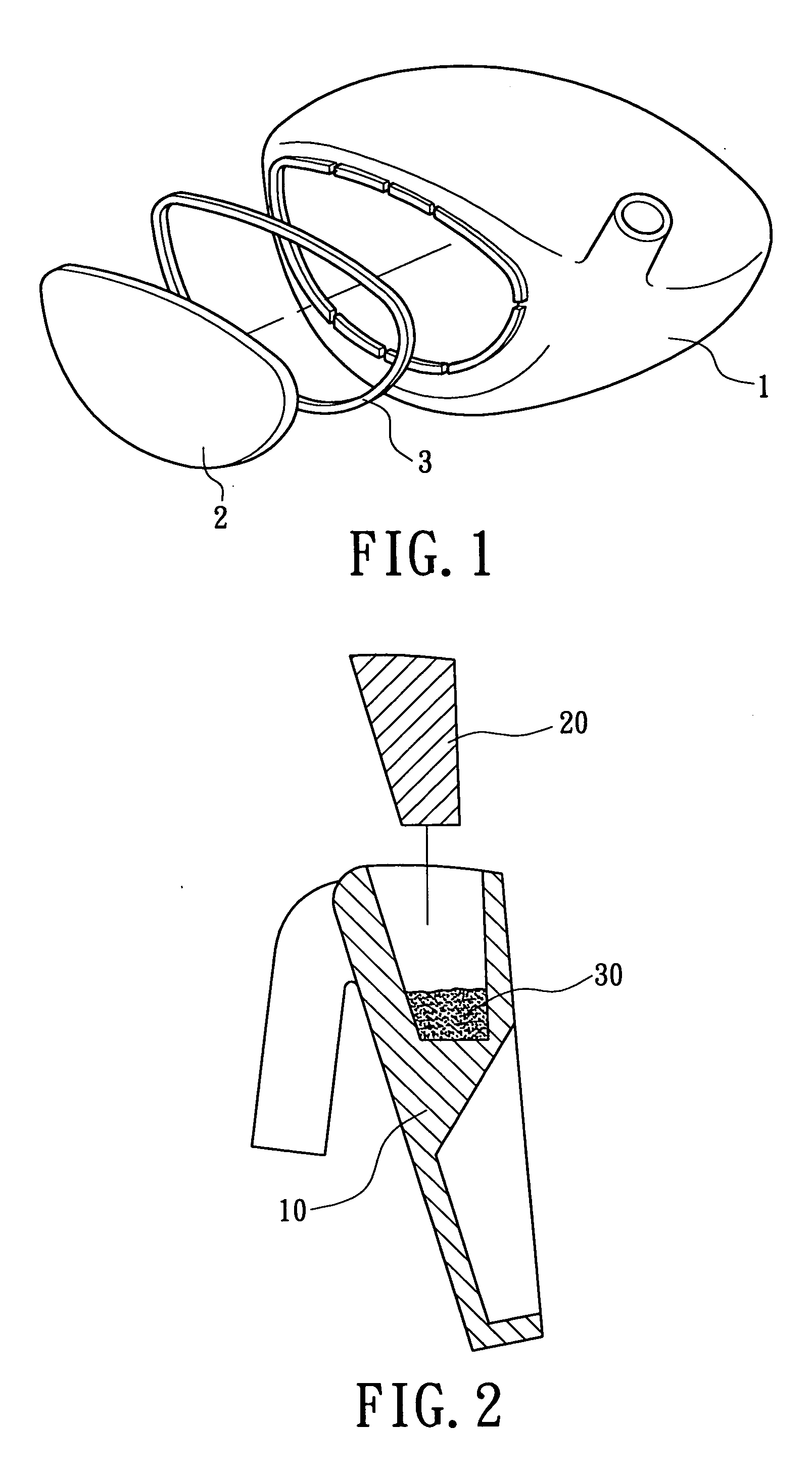
[0033]FIG. 1 illustrates an exploded view of using infrared rays for quick joining a golf club head in accordance with the present invention. The golf club head is consisted of a plurality of parts, which includes a main head body 1, a striking plate 2 and a metallic filler member 3. Subsequent to the main head body 1 combing with the striking plate 2, the metallic filler member 3 is disposed between the main head body 1 and the striking plate 2. Subsequently, infrared rays are used to heat and melt the metallic filler member 3. After cooling, the metallic filler member 3 can connect the main head body 1 with the striking plate 2. In this embodiment, the main head body 1 is made of stainless steel and the striking plate is made of titanium alloy. The material of the main head body 1 is selected from 17-4PH stainless steel, which performs high strength, corrosive-resistance and good wettability. The material of the striking plate 2 is selected from Ti-6Al-4V alloy, which performs hig...

second embodiment

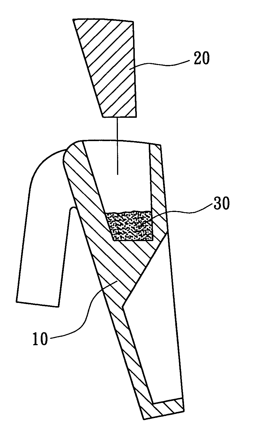
[0034]FIG. 2 illustrates an exploded view of using infrared rays for quick joining a golf club head in accordance with the present invention. The golf club head includes a main head body 10, a weight member 20 and a metallic filler member 30. The material of the main head body 10 is selected from a group consisted of titanium alloy, Fe-base alloy, magnesium alloy, aluminum alloy, Fe—Mn—Al alloy, shape memory steel, tungsten alloy, copper alloy, nickel alloy, bulk amorphous alloy, nano-alloy, composite material and ceramic material etc. The specific gravity of the weight member 20 is greater than that of the main head body 10, and selected from a group consisted of tungsten, tungsten alloy, copper alloy and lead alloy etc. The material of the metallic filler member 30 is selected from a group consisted of Ag-base fillers, Ni-base fillers, Cu-base fillers, or Ti-base fillers. Subsequent to the main head body 10 combing with the weight member 20, the metallic filler member 30 is dispos...


PUM

PropertyMeasurementUnit
wavelengthaaaaaaaaaa
melting pointsaaaaaaaaaa

Abstract

Using infrared rays for quick joining a golf club head adopts a heating source of infrared rays, which are used to melt metallic fillers disposed between a main head body and a striking plate. Thus, the striking plate is bonded to the main head body to constitute the golf club head.

Description

BACKGROUND OF THE INVENTION [0001] 1. Field of the Invention [0002] The present invention is related to using infrared rays for quick joining a golf club head. More particularly, the present invention is related to using infrared rays for heating the filler metal which is filled between a main head body and a striking plate to manufacture the golf club head. [0003] 2. Description of the Related Art [0004] The infrared ray has a frequency in the electromagnetic spectrum in the range just below that of red light. A quartz tube can radiate infrared rays in proportion to their temperature. The infrared ray is used to join separate objects within a small bonding area. Infrared joining can carry out rapid heating and cooling on the object. [0005] A conventional golf club head is consisted of a golf club head and a striking plate combined therewith. The joining method of the golf club head can be selected from a group of mechanically inserted method, glued method, welding method and brazin...

Claims


Application Information

Patent Timeline
Patent Type & Authority Applications(United States)
IPC IPC(8): A63B53/04A63B102/32B23K1/00B23K1/005B23K31/02
CPCB23K1/0008Y10T29/49826B23K1/0053
Inventor WU, SHYI-KAANSHIUE, REN-KAECHEN, CHAN-TUNG
Owner WU SHYI KAAN
Learn More