
Magnetic head device and method for making the same

Inactive Publication Date: 2005-02-10
TDK CORPARATION
View PDF3 Cites 2 Cited by
  • Summary
  • Abstract
  • Description
  • Claims
  • Application Information

AI Technical Summary

Benefits of technology

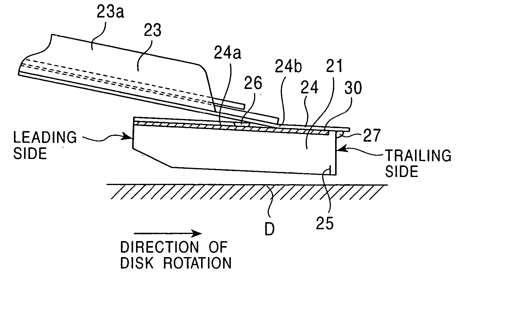
[0023] Consequently, a good electrical connection is maintained between the conductive resin and the support, and the electrical connection between the support and the slider is improved. Therefore, it is possible to provide a magnetic head device in which electrostatic discharge (ESD) is effectively suppressed in the thin-film element compared to the conventional magnetic head device.
[0024] In the present invention, the conductive resin may include a resin and a conductive filler mixed with the resin. In such a case, dielectric breakdown occurs between conductive filler particles. Consequently, the electrical connection between the slider and the support can be more effectively improved through the conductive resin and the region of the insulating layer in which dielectric breakdown is caused.
[0030] In the present invention, since dielectric breakdown is caused in the insulating layer lying under the conductive resin in step (c), a good electrical connection between the conductive resin and the support is ensured, and the electrical connection between the slider and the support can be improved compared to the conventional technique.
[0031] In the present invention, since dielectric breakdown is caused before step (b) of bonding the slider to the support, the step of causing the dielectric breakdown does not affect the thin-film element provided on the slider, and writing and / or reading characteristics of the thin-film element can be maintained satisfactorily.
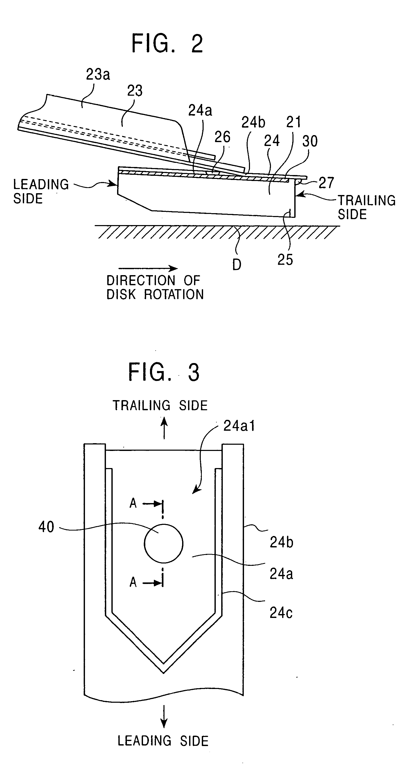
[0033] More specifically, preferably, an apparatus which is capable of both applying the conductive resin and applying the voltage is used, and after the conductive resin is applied by a nozzle of the apparatus, the voltage is applied to the insulating layer with the nozzle being pressed against the surface of the insulating layer lying under the conductive resin. In such a process, since the same apparatus can be used in the step of applying the conductive resin and the step of applying the voltage, the manufacturing time can be shortened and the manufacturing process can be simplified.
[0038] In accordance with the present invention, since dielectric breakdown is caused in the insulating layer lying under the conductive resin, a good electrical connection can be achieved between the conductive resin and the support, and thereby the electrical connection between the support and the slider can be improved. Therefore, it is possible to provide a magnetic head device in which electrostatic discharge (ESD) can be effectively suppressed in the thin-film element compared to the conventional technique.

Problems solved by technology

That is, the electrical connection between the slider 1 and the support 2 is extremely poor.

Method used


Image

  • Magnetic head device and method for making the same
  • Magnetic head device and method for making the same
  • Magnetic head device and method for making the same

Examples


examples

[0117]FIG. 15 is a graph showing the relationship between the resistance and the voltage applied between a slider and a support with respect to each of two magnetic head devices in which the slider and the support are bonded to each other by the first bonding method described above (Example 1). FIG. 16 is a graph showing the relationship between the resistance and the voltage applied between a slider and a support with respect to each of two magnetic head devices in which the slider and the support are bonded to each other by the third bonding method (Example 2). FIG. 17 is a graph showing the relationship between the resistance and the voltage applied between a slider and a support with respect to each of five magnetic head devices in which the slider and the support are bonded to each other by the second bonding method (Example 3). FIG. 18 is a graph showing the relationship between the resistance and the voltage applied between a slider and a support with respect to each of five ...


PUM


Abstract

A magnetic head device includes a slider including a thin-film element for writing and / or reading and a support for supporting the slider, the slider being bonded to a joint surface of the support at least partially with a conductive resin. A method for making the magnetic head device includes the steps of (a) applying the conductive resin at least onto a portion of an insulating layer formed on the joint surface of the support, (b) bonding the slider to the joint surface of the support with the conductive resin, and (c) causing dielectric breakdown in the insulating layer lying under the conductive resin before step (b) at the latest.

Description

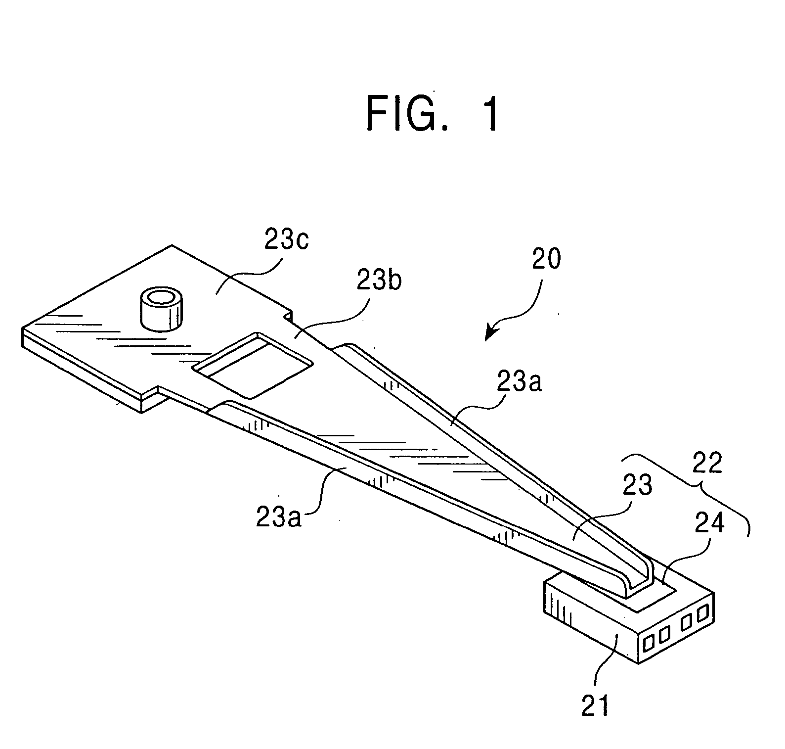
BACKGROUND OF THE INVENTION [0001] 1. Field of the Invention [0002] The present invention relates to a magnetic head device which is to be mounted in a hard disk drive or the like. More particularly, the invention relates to a magnetic head device in which a good electrical connection between a slider and its support is ensured and electrostatic discharge is prevented from occurring in a thin-film element for writing and / or reading provided on the slider and to a method for making the magnetic head device. [0003] 2. Description of the Related Art [0004] A conventional magnetic head device which is to be mounted in a hard disk drive or the like has, for example, a structure shown in FIG. 21. [0005] The magnetic head device includes a slider 1 and a support 2 for supporting the slider 1. [0006] The slider 1 is composed of a ceramic or the like. As shown in FIG. 21, a thin-film element 3 for writing and / or reading is provided on the trailing side of the slider 1. [0007] The support 2 i...

Claims


Application Information

Patent Timeline
IPC IPC(8): G11B5/48G11B5/31G11B5/60G11B21/21
CPCG11B5/4826
Inventor SATO, AKIHIROSATOH, HIDEZI
Owner TDK CORPARATION
Learn More