
Low temperature polycrystalline silicon type thin film transistor and a method of the thin film transistor fabrication

a technology of polycrystalline silicon and thin film transistor, which is applied in the direction of silicon, electrical equipment, semiconductor devices, etc., can solve the problems of reducing the average mobility of charge carriers, complicated process of forming transistors of driving integrated circuits, and inability to form integrated circuits on amorphous silicon thin films. , to achieve the effect of reducing the problem

Inactive Publication Date: 2005-01-20
SAMSUNG DISPLAY CO LTD
View PDF1 Cites 17 Cited by
  • Summary
  • Abstract
  • Description
  • Claims
  • Application Information

AI Technical Summary

Benefits of technology

[0013] Accordingly, an object of the present invention is to provide a polycrystalline silicon type thin film transistor and a method of fabricating the thin film transistor to diminish the problems generated from the dangling bond in the channel region of thin film transistor.
[0014] It is other object of the present invention to provide a polycrystalline silicon type thin film transistor improved in the carrier mobility in the channel region of thin film transistor and thus improved in the speed of operation of thin film transistor.
[0015] It is another object of the present invention to provide a polycrystalline silicon type thin film transistor improved in the value of threshold swing in a thin film transistor.
[0018] Referring to the specific method for oxidizing the amorphous silicon layer, the method of spontaneous diffusion and the method of forced injection can be used. The method of spontaneous diffusion can be done by placing the substrate deposited with amorphous silicon layer in clean air condition or oxygen gas during a predetermined time period of more than 6 hours or more preferably 24 hours. The method of forced injection can be done by the steps of supplying gases including oxygen atom in process chamber, generating plasma including oxygen atom or radicals by resolving the gases and injecting the oxygen atom or radicals into amorphous silicon layer. In the plasma type oxidation, the RIE (reactive ion etching) method is not considered because the peak value of oxygen concentration is shown far below the surface and only the surface layer of 100 Å is in our concern. The method of forced injection can also be done by heating the substrate up to the temperature about 300° C. and increasing the speed of diffusion of oxygen atom into the amorphous silicon layer.

Problems solved by technology

Thus, the integrated circuits cannot be formed on the amorphous silicon thin film of which the active region of pixel transistor of LCD is made.
And, the fact that driving integrated circuit generally has both p type channel transistor and n type channel transistor makes the process of forming transistors of driving integrated circuit and the process of forming LCD more complicated.
These defects decrease the average mobility of charge carrier in the channel of polycrystalline silicon type thin film transistor by capturing the charge carrier when the source / drain current flows.
Thus, the defects lower the speed of operation in the transistor.
Thus, in the channel region of polycrystalline silicon type thin film transistor, a considerable amount of charge carrier electrons is to be captured during the operation of the transistor and that lowers the conductivity of channel and the speed of operation of the transistor.
But, the silicon-hydrogen bond made in these method of containing hydrogen in the polycrystalline or amorphous silicon has low bond energy.
This is caused by the fact that the heat generated during the operation of polycrystalline silicon type thin film transistor stimulate the hydrogen atoms to have the tendency of being volatilized.
And this naturally lowers the reliability of integrated circuit device having the polycrystalline silicon thin film transistor.

Method used


Image

  • Low temperature polycrystalline silicon type thin film transistor and a method of the thin film transistor fabrication
  • Low temperature polycrystalline silicon type thin film transistor and a method of the thin film transistor fabrication
  • Low temperature polycrystalline silicon type thin film transistor and a method of the thin film transistor fabrication

Examples


Embodiment Construction

[0027] Hereinbelow, a few embodiment of the top gate type polycrystalline silicon thin film transistor and a few embodiment of the method of forming the thin film transistor according to the present invention will be described.

[0028] Referring to FIG. 1, on the glass substrate (10), a blocking layer (11) is formed with silicon nitride and an amorphous silicon layer (13) is deposited on the blocking layer (11). The amorphous silicon layer (13) is formed by low temperature CVD under the temperature of 400° C.

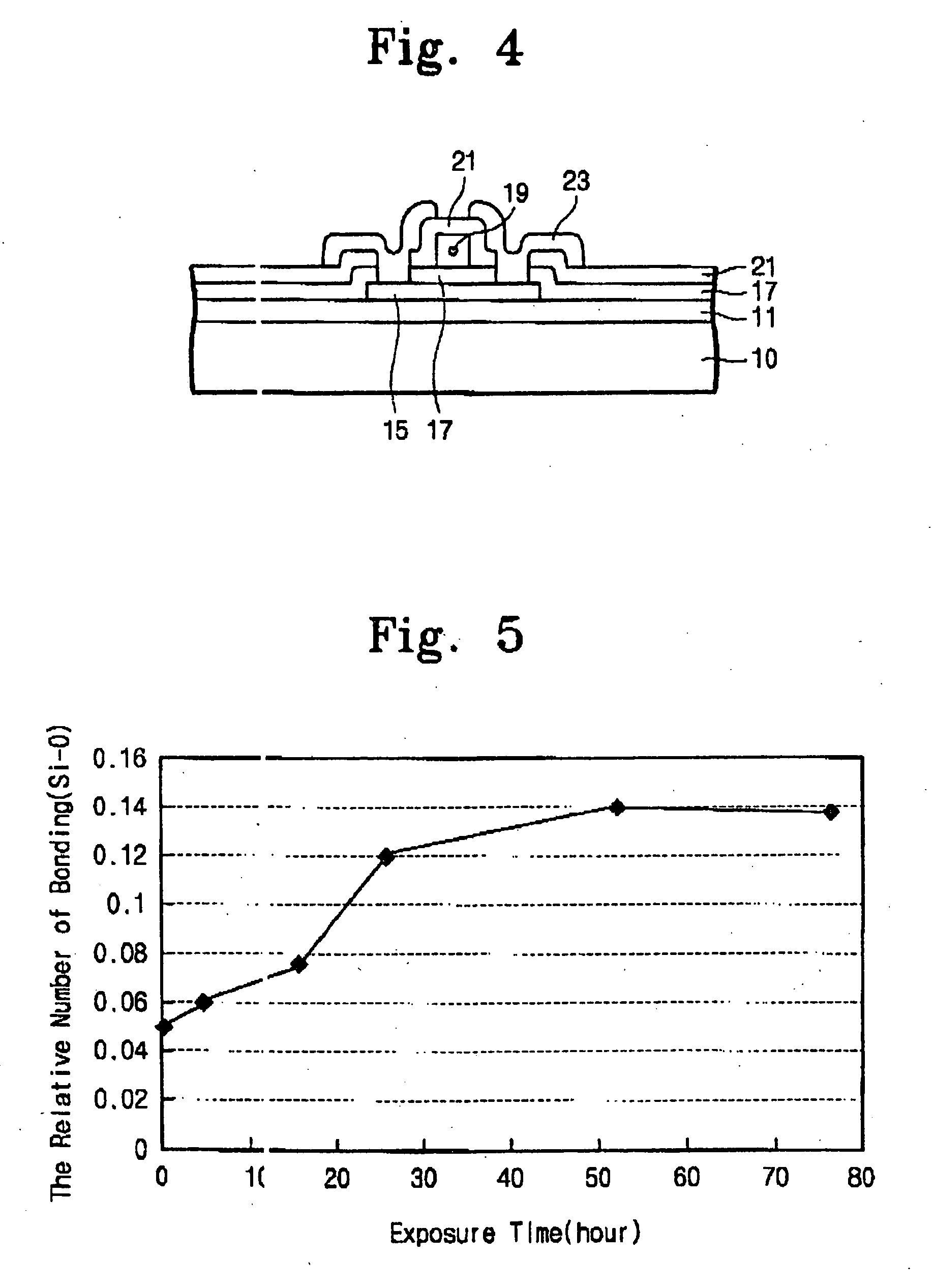
[0029] Referring to FIG. 2, the substrate (10) deposited with amorphous silicon layer (13) is exposed to clean air or oxygen gas for at least 6 hours or more favorably 24 hours. in the mean time, oxygen atoms are diffused into the amorphous silicon layer (13′) and make loose bond with silicon atom and form a nature oxide layer at the surface of the amorphous silicon layer (13′). As the time pass, the number of silicon-oxygen bond increase but with decreasing ratio and finally st...


PUM


Abstract

A method of fabricating poly crystalline silicon type thin film transistor is disclosed. In the method, before the step of re-crystallization of amorphous silicon to form polycrystalline silicon active pattern, a step for injecting predetermined amount of oxygen atom into the surface part of the amorphous silicon layer. By this addition of step, the surface part of the silicon layer is to be oxidized and the crystal defect in the interface between the gate insulating layer and poly crystalline silicon layer can be cured and the mobility of charge carrier can be improved in the channel of the thin film transistor.

Description

[0001] This application relies for priority upon Korean Patent Application No. 2000-03467, filed on Jan. 25, 2000 and No.2000-23111, filed on Apr. 29, 2000, the contents of which are herein incorporated by reference in their entirety. FIELD OF THE INVENTION [0002] The present invention relates generally to a low temperature polycrystalline silicon type thin film transistor and a method of fabricating the thin film transistor, and is directed more particularly to the thin film transistor which can increase the mobility of charge carrier and the method of fabricating the thin film transistor. BACKGROUND OF THE INVENTION [0003] Thin film transistor used in LCD (Liquid Crystal Display) can be divided into two types, amorphous silicon type and polycrystalline silicon type, by material structure of silicon thin film. [0004] In considering that the glass substrate used in LCD panel cannot sustain the flat state in high temperature process, the amorphous silicon type thin film transistor is...

Claims


Application Information

Patent Timeline
IPC IPC(8): H01L21/20C01B33/02H01L21/336H01L29/786
CPCH01L29/66757H01L29/78696H01L29/78675
Inventor MOON, KOOK-CHULKIM, HYUN-DAEMIN, HOON-KEE
Owner SAMSUNG DISPLAY CO LTD
Learn More