
Resin composition having high dielectric constant and uses thereof

a technology of dielectric constant and composition, applied in the field of resin composition having a high dielectric constant, can solve the problems of large wiring area of processing, inability to meet the requirements of a build-up technique, and technical means, however, have limitations

Inactive Publication Date: 2005-01-13
ETERNAL MATERIALS CO LTD
View PDF7 Cites 11 Cited by
  • Summary
  • Abstract
  • Description
  • Claims
  • Application Information

AI Technical Summary

Benefits of technology

[0027] The filler used in the subject invention may be a conductive or non-conductive inorganic material, or metal or resin powder. The filler may also be helpful in enhancing the dielectric constant of a capacitor material.
[0029] The subject invention further relates to a process for manufacturing a printed circuit board, comprising using the composition of the subject invention as a capacitor material embedded in the printed circuit board. The use of the composition of the subject invention in the production of a printed circuit board not only avoids the problem associated with the brittleness of the material due to the increase in the filling amount of ceramic powder for enhancing the dielectric constant, but also obtains a printed circuit board in which a capacitor having a high dielectric constant is embedded.

Problems solved by technology

However, this ROC patent does not mention what the materials useful in said dielectric layer are.
Such processing requires a larger wiring area and is not suitable for a build-up technique, which manufactures multi-layer printed circuit boards having small wire width and space and including blind holes.
This technical means, however, has an limitation.
Under such a low temperature, the ferro-electric ceramic powder cannot form a high dielectric constant lattice.
Therefore, the dielectric constant of the capacitor material embedded in a printed circuit board can not be high.
Moreover, although it is workable to enhance the dielectric constant by increasing the filling amount of the ceramic powder, the filling amount is often limited.
If the filling amount is too high, the material becomes brittle and easily fractures, and thus is not suitable in the manufacture of printed circuit boards.
Even though the use of nanopowders can enhance the filling density, thereby increasing the dielectric constant, the handling of the nanopowders is difficult.
Moreover, since the viscosity of the resin liquid is increased due to the increase in specific surface area, it makes the filling more difficult and the filling amount will be extensively reduced.
Nonetheless, this technique also faces the problems associated with the filling technology of polymer powder, the controlling of rheological property of a resin material, and the dependency of material on temperature and humidity, and cannot obtain satisfactory results.
Moreover, since the upper limit of the volume fraction of the ceramic powder (Vp) is 50% or 60% and the dielectric constant of the ceramic powder (Kp) cannot be effectively increased due to the insufficiently high processing temperature, the dielectric constant of the capacitor material cannot be increased.

Method used

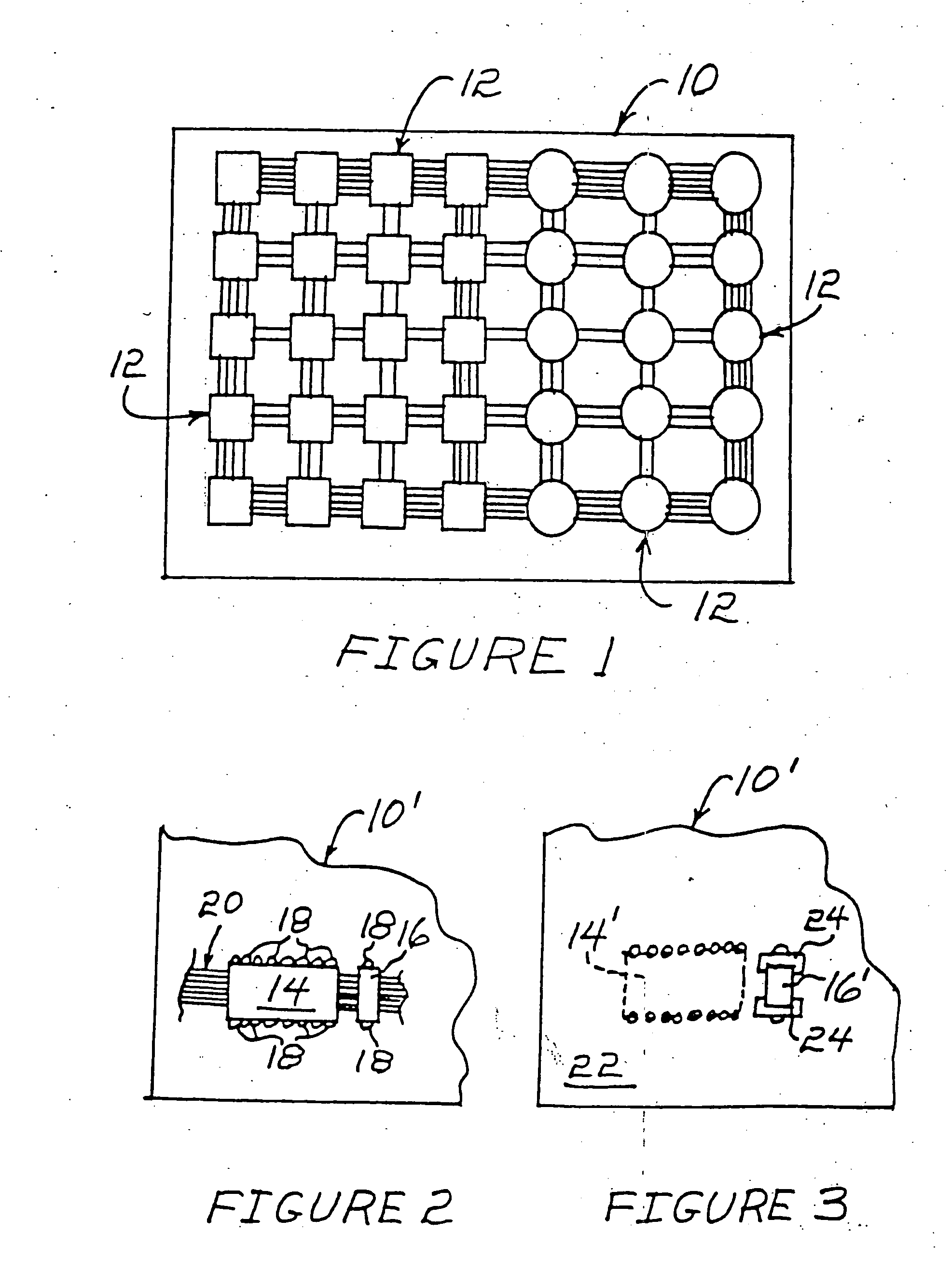
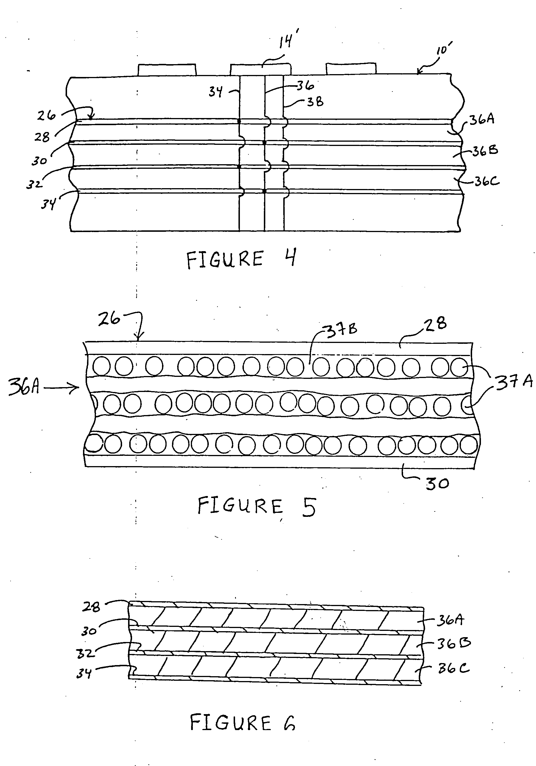
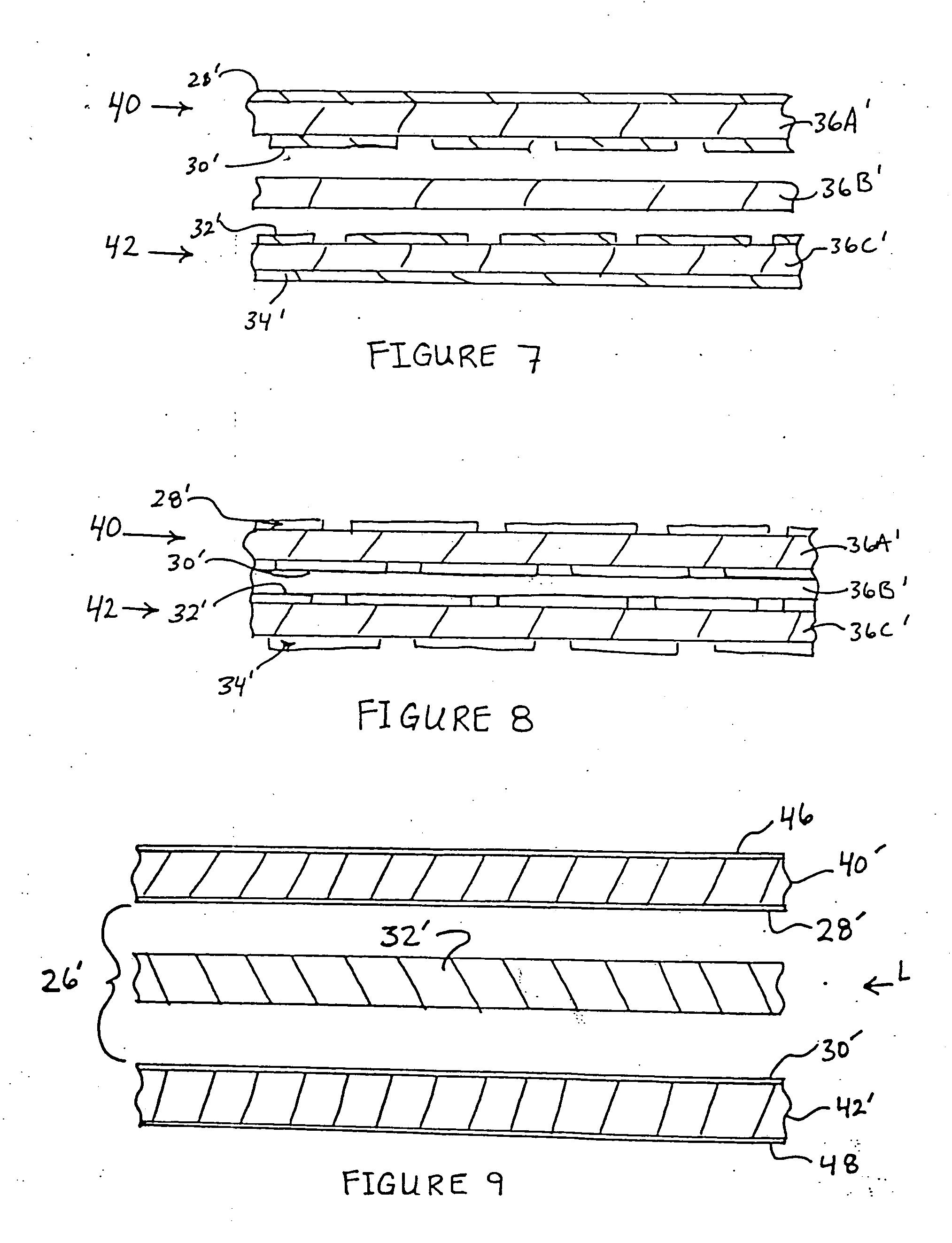

Image

  • Resin composition having high dielectric constant and uses thereof
  • Resin composition having high dielectric constant and uses thereof
  • Resin composition having high dielectric constant and uses thereof

Examples


examples

[0031] Table 1 lists the components of the formulation of each example. Formulation 1 is a control formulation without a highly polar modifier and ceramic powder. Formulations 2 to 6 incorporated highly polar modifiers in different proportions. Formulations 8 to 12 incorporated both ceramic powders and highly polar modifiers in different proportions.

TABLE 1The Components of FormulationsCuring agentHighly polarCeramicBisphenol A(methylCuring agentmodifierSolventpowderepoxy resinhexahydrophthalic(N′,N′-dimethyl(cyano resin(dimethyl(BaTiO3 [XJ-(EPSON 828)anhydride)benzylamine)[CR-S])foramide4000])F120200.06˜˜˜F220200.0626˜F320200.06412˜F420200.06618˜F520200.06824˜F620200.061236˜F720200.06˜˜120F820200.0626126F920200.06412132F1020200.06618138F1120200.06824144F1220200.061236156

Unit: gram

F: formulation

[0032] Experimental procedure:[0033] 1. Stoichiometric epoxy resin, curing agent, highly polar modifier, ceramic powder and solvent were added to a container equipped with a stirrer and w...


PUM

PropertyMeasurementUnit
particle sizeaaaaaaaaaa

Abstract

The subject invention relates to a resin composition having a high dielectric constant, comprising (a) an epoxy resin, (b) a curing agent, (c) a ceramic powder, and (d) a highly polar modifier. The subject invention further relates to a process for the manufacture of a printed circuit board comprising using the composition of the subject invention as a material for a capacitor material embedded in the printed circuit board.

Description

FIELD OF THE INVENTION [0001] The present invention relates to a resin composition having a high dielectric constant and uses thereof. BACKGROUND OF THE INVENTION [0002] With the development of technology, various electronic products are designed to be lighter, thinner, shorter, smaller, and multi-functional. However, due to the increase in the number of various passive elements, especially the surface mount design (SMD) elements, e.g., resistors, capacitors, and inductometers, used on a printed circuit board, hundred of passive elements occupy an extremely large area on the surface of the printed circuit board even though their sizes have been continuously reduced. In order to eliminate such drawback, the passive elements are manufactured in a form of a film and then embedded in circuit boards, so as to effectively reduce the area 10 to 20 times and enhance the reliability due to reduced soldering points. [0003] In the past, there were many researches as to embedding a capacitor in...

Claims


Application Information

Patent Timeline
Patent Type & Authority Applications(United States)
IPC IPC(8): C08K3/22C08L63/00H05K1/16
CPCC08K3/22C08L63/00H05K1/162H05K2201/0209H05K2201/0355H05K2201/09309C08L2666/20
Inventor HSU, TSAI FASHIH, YING-TINGTSAI, MING-YI
Owner ETERNAL MATERIALS CO LTD
Learn More