Data recording method, data recording equipment and data recording evaluation equipment

a data recording and data recording technology, applied in recording signal processing, instruments, television systems, etc., can solve the problems of difficult to maintain timing accuracy less than hundreds of picoseconds, direct influence of conventional control methods, etc., and achieve high accuracy

Inactive Publication Date: 2005-01-13
HITACHI LTD +1
View PDF7 Cites 9 Cited by
  • Summary
  • Abstract
  • Description
  • Claims
  • Application Information

AI Technical Summary

Benefits of technology

[0006] A conventional method for control of alternating duration Tpw and duration Tpb so that Tpw and Tpb appear at a given ratio during a bit period T of recording data shown in FIG. 2 is to set time to start and time to stop each pulse by using a plurality of fixed delay lines or by using the output from a tap that is proximate to a target position, one of the taps of closely spaced steps of a multistage delay block, and thereby generating write pulses. Particularly, a pulse edge jitter has a great effect on reading jitter and, therefore, higher timing accuracy is required for high-speed recording that will advance in future. However, the conventional control method is directly affected by temperature characteristics and variation in delay lines. Thus, even if calibration is performed in measuring length of T in units of stages or steps, it is difficult to maintain timing accuracy less than hundreds of picoseconds.
[0008] In view of the above discussion, it is an object of the present invention to provide data recording equipment and a data recording method that can generate write pulses adaptively for and following inconstant disk revolution and change in liner velocity and record data signals, using a high-frequency clock.
[0012] Use of the invented method enables a clock accuracy of 25 ps in the case of a 40 GHz clock which is used at a 40 Gbps transfer rate. However, in the optical disk segment, multi-pulsing requires a plurality of data signals to be synchronized and output. It is conceivable to use a plurality of multiplexers in order to output a plurality of data signals. In this case, synchronizing the plurality of multiplexers and timing alignment across the plurality of data signals are difficult. The commonly used multiplexer configuration for multiplexing m pieces of input signals eventually to one output signal is changed to a configuration for multiplexing the m pieces of input signals to n pieces of output data signals. By using a single source of generating a clock to be used for multiplexing to the n pieces of output data signals, synchronization of the n pieces of output signals can easily be ensured.
[0014] Instead of a normal m:1 multiplexer (to generate one output signal from m pieces of input signals), the m:n multiplexer is configured to generate n-pieces of output signals and used for multipulse generation. An internal clock ensures signal synchronization within the m:n multiplexer IC, data transfer starts at the same timing and the circuit operates without a problem. Moreover, because of a high distance accuracy of n pieces of output lines, the n-pieces of output signals through the output lines from the m-n multiplexer have even delay amounts and data is easy to pass to a port of an entity for subsequent operation. The n pieces of output signals need not be transferred at only a single rate; a variable rate of transfer may be used, according to application.
[0015] The m:n multiplexer includes a clock multiplier function to multiply a low-speed clock which is used for input data to the m:n multiplexer by a factor of n and generate a high-speed clock. Multiplexing and latching are performed, based on this high-speed clock, and, consequently, pulse positional accuracy can be enhanced. Because only the low-speed clock is used for input from the external, the high-speed clock is not handled externally and high accuracy pulses can be generated. Furthermore, by outputting the clock that must be used within the multiplexer to the external when data is read, high frequency convolution can be used to decrease laser diode noise. By the switches 14-1, 14-2, . . . , 14-n of the current sources 13-1, 13-2, . . . , 13-n which are controlled with the n-pieces of synchronous high-speed pulses supplied thereto, the amount of current flowing through a laser diode 12 whose light beam output changes, depending on the current amount, is adjusted, and the laser diode is able to generate optical multipulse signals at a high speed.
[0017] According to the present invention, high-speed pulses of n pieces of synchronous data signals can be generated with high accuracy in order to record data on optical disks or optically-assisted magnetic disks by using multipulse or multilevel signals.

Problems solved by technology

However, the conventional control method is directly affected by temperature characteristics and variation in delay lines.
Thus, even if calibration is performed in measuring length of T in units of stages or steps, it is difficult to maintain timing accuracy less than hundreds of picoseconds.
In this case as well, a method of changing the delay amount according to a position with respect to the radial direction of a disk, using the above multistage delay block, is conceivable, but, it is still difficult to maintain timing accuracy less than hundreds of picoseconds.

Method used


Image

  • Data recording method, data recording equipment and data recording evaluation equipment
  • Data recording method, data recording equipment and data recording evaluation equipment
  • Data recording method, data recording equipment and data recording evaluation equipment

Examples


embodiment 1

[0044] [Embodiment 1]

[0045] A preferred Embodiment 1 of the invention wherein a 4:2 multiplexer is applied to generating multipulse signals is discussed, using FIGS. 7 through 9. FIG. 7A is a schematic diagram for explaining a flow of processing up to writing signals corresponding to data to be recorded on an optical disk. FIG. 7B is a schematic of a pulse shaping circuit. FIG. 8 is a schematic showing an example of the 4:2 multiplexer according to the present invention. FIG. 9 is an explanatory diagram showing an example of multipulse composition.

[0046] As shown in FIG. 7A, input data (data to be recorded) 22 is encoded by an encoding circuit 23 and a recording pulse shaping circuit 10 converts signals into which the data is encoded into signals to form a strategy for writing on an optical disk 24. The thus converted signals are signals programmed to be multiplexed and a sequence of four data signals Din1 to Din4 which are serially connected in order of 1 to 4 is input to the 4:2 ...

embodiment 2

[0051] [Embodiment 2]

[0052] A preferred Embodiment 2 of the invention wherein a 4:2 multiplexer is applied to generating multilevel signals is discussed. FIG. 10A is a schematic showing an equipment configuration example for generating a multilevel signal. FIG. 10B is a signal waveform diagram showing an example of 4-valued multilevel signal composition.

[0053] While a signal consisting of two values is output in Embodiment 1, Embodiment 2 enables output of a high-speed signal consisting of three or more values. As shown in FIG. 10A, input data is encoded into signals which are, in turn, converted into multilevel signals to be written on a disk. The thus converted signals are signals programmed to be multiplexed and input to the 4:2 multiplexer 11 from which two Dout1 and Dout2 signals are output. These two Dout1 and Dout2 output data signals which are synchronized and have even delay amounts are level converted by level converters 28-1 and 28-2, respectively, and then, combined thr...

embodiment 3

[0056] [Embodiment 3]

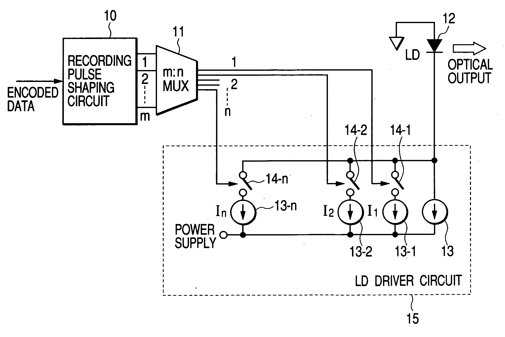
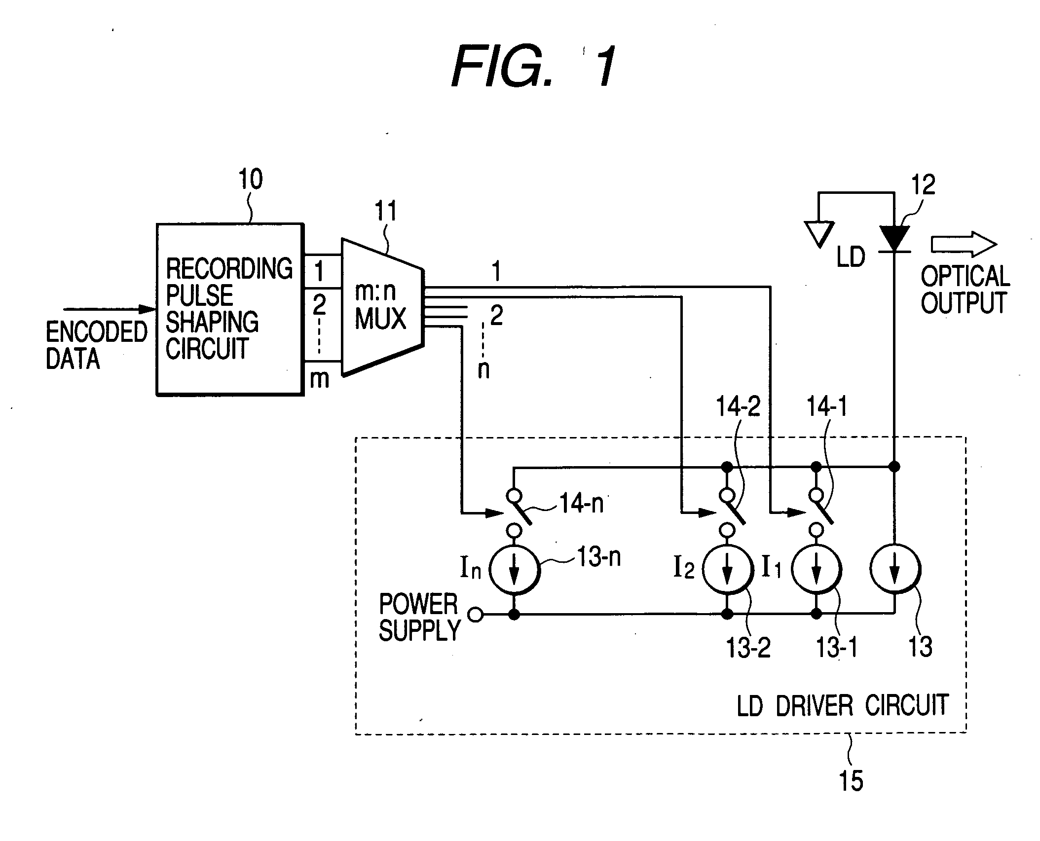
[0057] A preferred Embodiment 3 of the invention wherein the speed of n-pieces of output data signals from an m:n multiplexer is n times as much as the speed of input data signals and the n pieces of output data signals are at different speeds is discussed with reference to FIGS. 11 and 12. FIG. 11 is a diagram showing a write strategy example (with four power levels). FIG. 12 is a schematic showing one example of the m:n multiplexer according to the present invention.

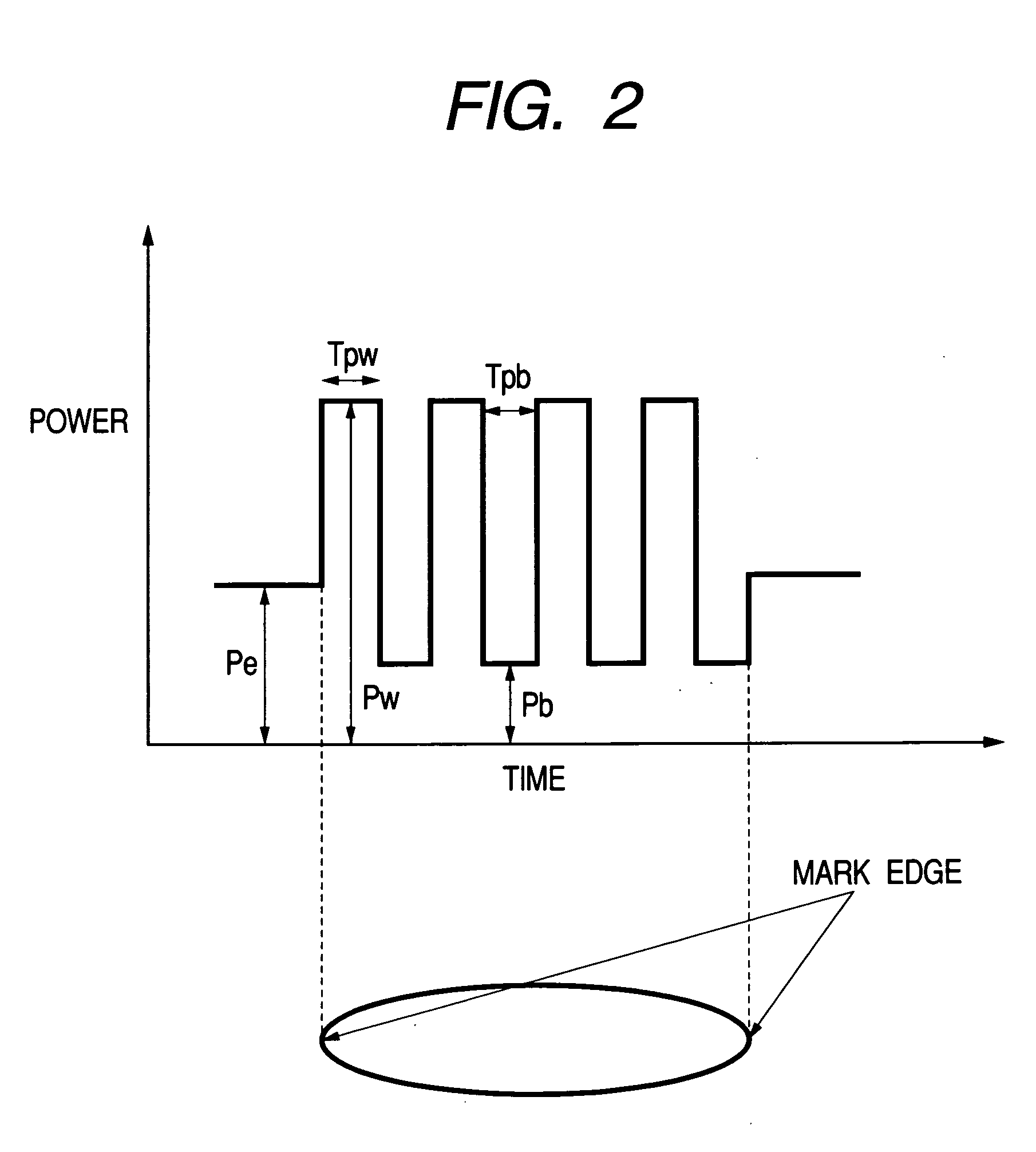
[0058] If the strategy shown in FIG. 11 is required, a high positional accuracy is required for Pe and Pw1 which are programmed to form recording mark edges for edge recording, but the positional accuracy of Pw2 which is a medium level within the strategy need not be so high as Pe and Pw1. A configuration example of the m:n multiplexer that can meet this requirement is shown in FIG. 12.

[0059] A concrete instance where a 4T write strategy shown at the bottom of FIG. 11 is created is discussed. As ...


PUM


Abstract

Information recording equipment of the present invention includes a multiplexer to generate n pieces of synchronous high-speed pulses. Instead of a normal m:1 multiplexer configuration for parallel-serial conversion, an m:n multiplexer configuration is used which generates m pieces of output signals from n pieces of input signals. The recording equipment including the m:n multiplexer enables high-resolution and high-speed pulse generation and carries out multipulse and multilevel signal generation.

Description

FIELD OF THE INVENTION [0001] The present invention relates to high-speed pulse generation in optical disk storage equipment such as CD-R drive, CD-RW drive, DVD-R drive, DVD-RW drive, DVD-RAM drive, and Blu-ray drive devices which drive and control multi-leveled and multi-pulsed optical modulation waveforms when recording data on data recording media and data recording evaluation equipment. [0002] The present invention also relates to high-speed pulse generation in a data recording method in the field of magnetic recording, by which data is recorded by intermittently heating a data recording medium by irradiating the medium with laser beam pulses in synchronization with a reference clock for recording, while applying a magnetic field with polarity being reversed in accordance with data to be recorded in synchronization with the reference clock. BACKGROUND OF THE INVENTION [0003] With a great increase in the capacity of optical disk storage equipment, there is an urgent need to incr...

Claims


Application Information

Patent Timeline
IPC IPC(8): G11B5/09G11B7/0045G11B7/125G11B20/14
CPCG11B5/09G11B7/0062G11B7/24088G11B2005/0021G11B11/10528G11B11/1053G11B20/1403G11B11/10521
Inventor WATANABE, KOICHIMINEMURA, HIROYUKI
Owner HITACHI LTD
Why Eureka
Try Eureka