
Method of thermoforming fiber reinforced thermoplastic sandwich panels, thermoformed articles, and modular container structure assembled therefrom

Active Publication Date: 2004-06-17
ADVANCED COMPOSITE STRUCTURES LTD
View PDF14 Cites 43 Cited by
  • Summary
  • Abstract
  • Description
  • Claims
  • Application Information

AI Technical Summary

Benefits of technology

[0012] Specifically, a localized area of the FRTP skin and core panel is thermoformed and consolidated into an article having a localized region of homogeneous thermoplastic melt. In the preferred embodiment, the localized area of panel is configured into at least three optimized designs including: an angled core transition to a radiused skin-core edge; an angled core transition to a flat, or non-radiused skin-core edge; a radiused and angled core transition to a radiused skin-core comer. The core-skin edge and comer areas so thermoformed and consolidated is comprised of the reinforcing fibers of the FRTP skins and the TP matrix-binder of both the FRTP skins and TP core. Thus, as a localized and consolidated laminate area of the sandwich panel, the homogenous melt region advantageously benefits from the increased weight ratio of TP matrix-binder to fiber due to the contribution of matrix-binder of the core as opposed to the TP matrix-binder of the FRTP skins alone. This is accomplished without removal of the original raw stock panel material and without the addition of reinforcing materials to the localized areas, rather by transforming the thermoplastic into an optimized structural form and configuration.
[0028] Maximized useful container volume loading due to elimination of fastener protrusion into the load volume and elimination of internal stiffening members required with monocoque structures.

Problems solved by technology

This improvement further results in individual repair and replacement of damaged modular container components rather than replacement of the entire container structure.

Method used


Image

  • Method of thermoforming fiber reinforced thermoplastic sandwich panels, thermoformed articles, and modular container structure assembled therefrom
  • Method of thermoforming fiber reinforced thermoplastic sandwich panels, thermoformed articles, and modular container structure assembled therefrom
  • Method of thermoforming fiber reinforced thermoplastic sandwich panels, thermoformed articles, and modular container structure assembled therefrom

Examples


Embodiment Construction

:

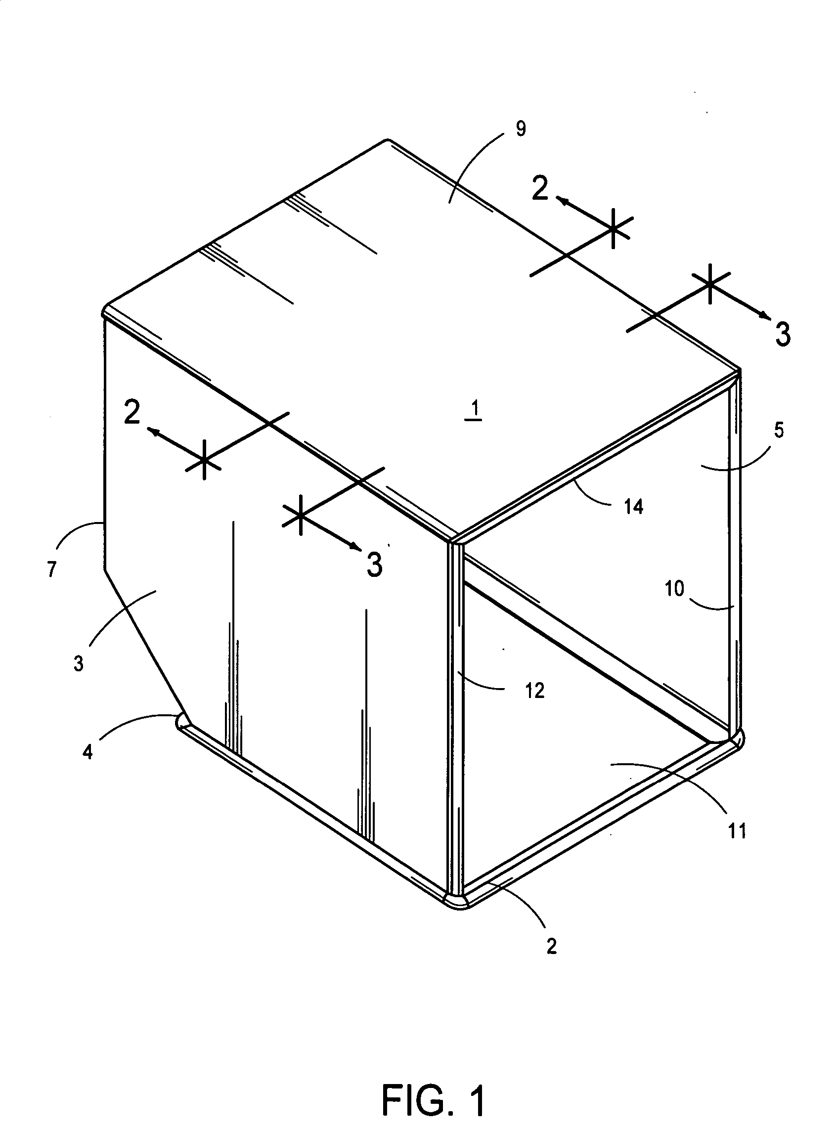
[0040] FIG. 1 illustrates a schematic perspective view of a container as may be used by example for air cargo applications. The general shape, geometry and scale of the figure is not limiting of the invention's scope or application to air cargo applications; in contrast to sea, land and intermodal containers; rather is shown to aid in the invention's disclosure. Container 1 has a forward end 2 and rearward end 4.

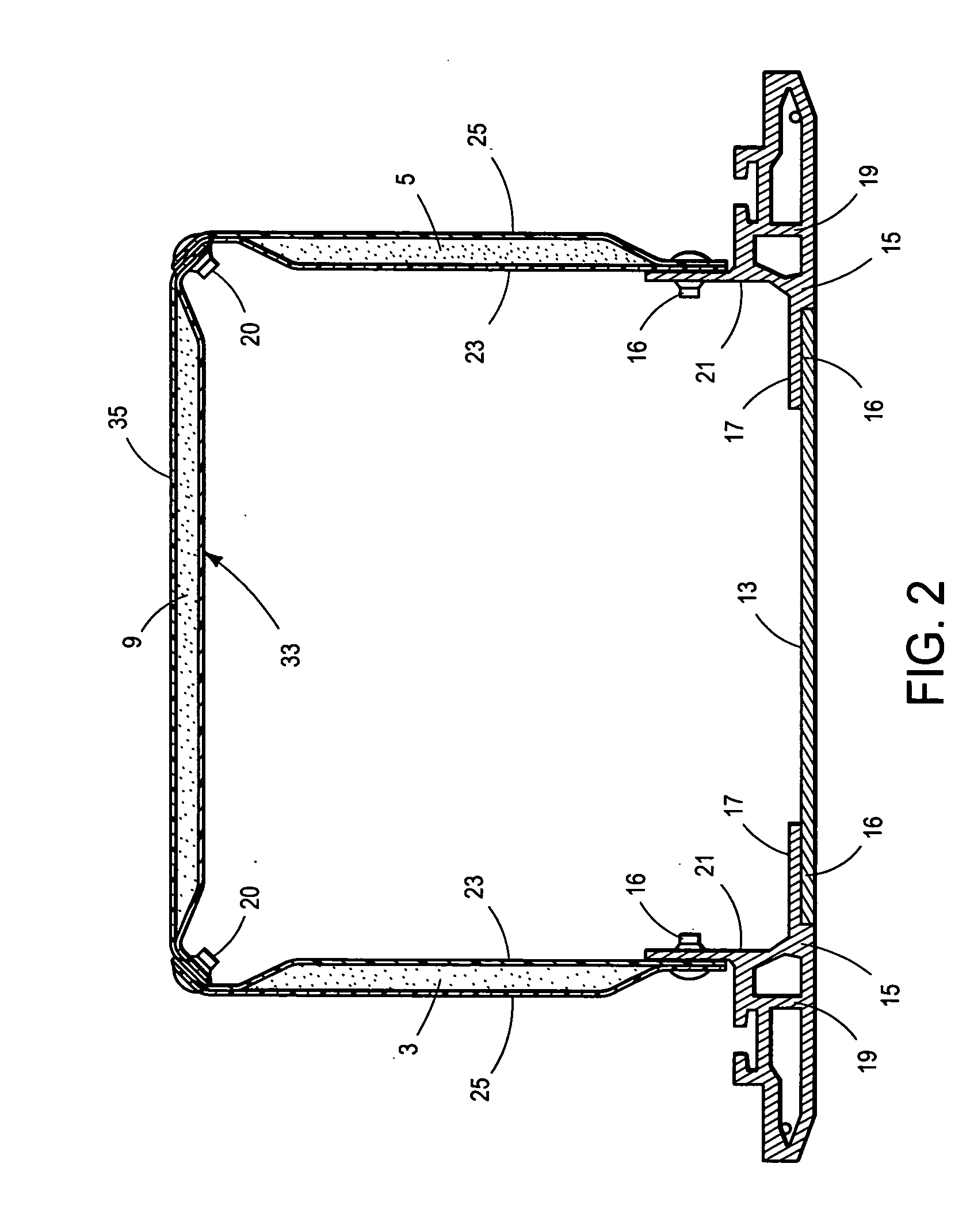
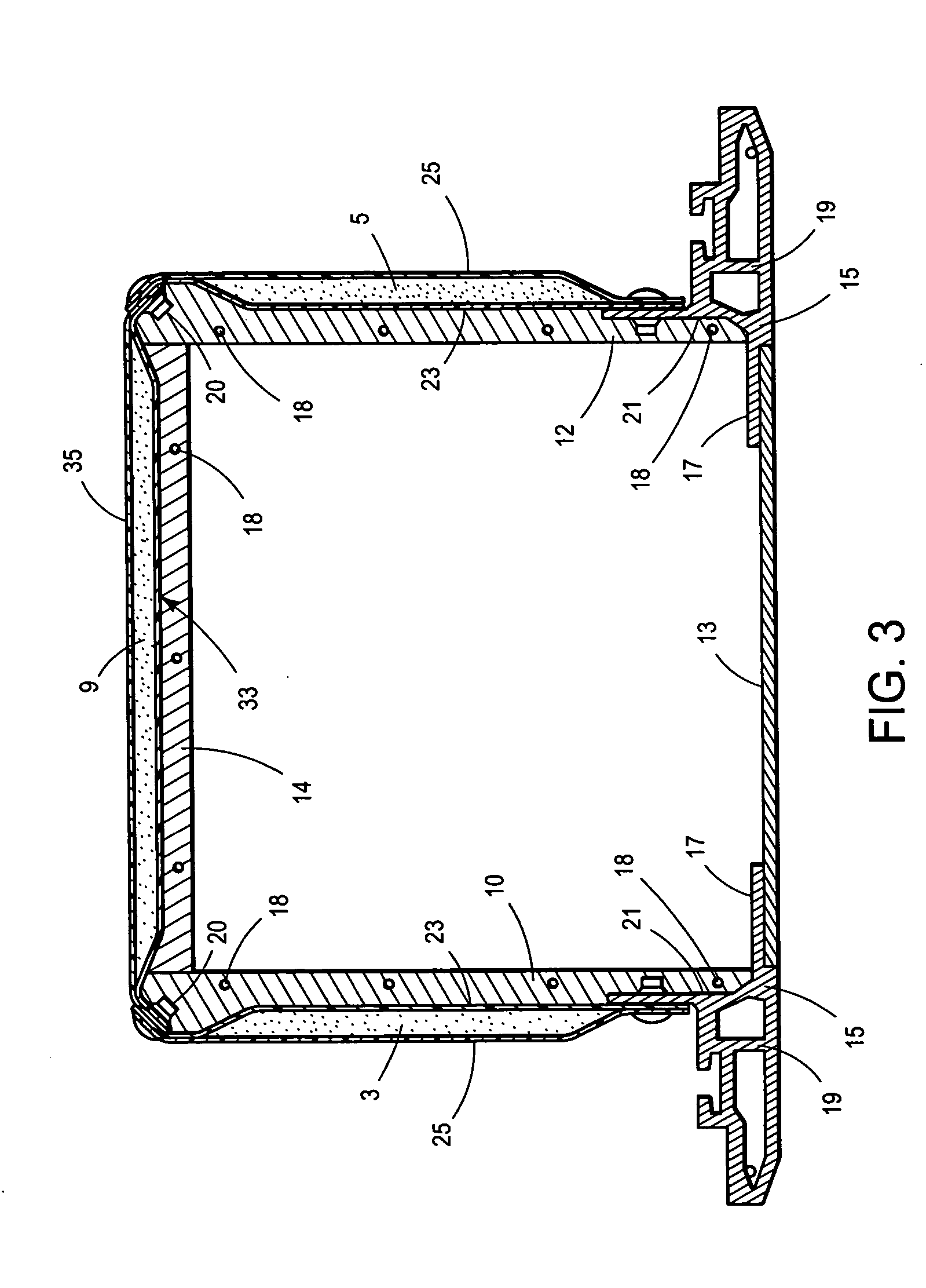
[0041] Container 1 further has two side walls 3 and 5, rear wall 7, top wall 9, base 11 and with opening 6 at forward end 2 which is framed by: base 11; elements 10, 12, 14; and the forward termination of sides 3 and 5, and top 9, opening 6 serving as an access to the interior of the container. Elements 10, 12 and 14 serve as hardware framing members at opening 6 at the forward termination of walls 3, 5 and 9.

[0042] In the inventive embodiment of container 1, walls 3, 5, 7 and 9 are sandwich panels constructed of Fiber Reinforced Thermoplastic (FRTP) skins and low-density c...


PUM


Abstract

A method is disclosed utilizing off the shelf constant cross section thickness sandwich panels comprised of Fiber Reinforced Thermoplastic (FRTP) resin skins and low density thermoplastic (TP) core material wherein the steps of selectively and controllably exposing the panels to heat and incrementally thermoforming the skin-core into a consolidated composite edge or intra-panel area in consideration of subsequent mating and attachment of the FRTP sandwich panel to other structures is achieved. The exact configuration of articles so thermoformed is design optimized to overcome manufacturing, assembly, weight, in-service and structural performance shortcomings of prior art and FRP sandwich panel structures. Further disclosed is an improved, load-bearing, modular design container structure assembled from such thermoformed FRTP sandwich panels in which is utilized the unique core-skin edge configuration of the present invention in consideration of improved: load bearing performance, useful load volume, reduced manufacturing costs, structural weight savings, impact and damage tolerance and repair and replace issues.

Description

BACKGROUND:[0001] 1. Field of the Invention[0002] The present invention relates generally to thermoforming of sandwich panels comprised of fiber reinforced thermoplastic (FRTP) skins and low-density core of a thermoplastic material, thermoformed articles made therefrom, and more particularly an assembled container structure comprised of the thermoformed FRTP sandwich panels and attachment hardware.[0003] 2. Reference to Prior Art[0004] Container structures such as those used for land, sea and air transport of goods having multi-piece metallic constructions are known. These structures make use of monocoque designs wherein relatively thin gage sheets forming a shell are mechanically fastened to angle, hat-section, doublers or similar stiffening elements. The monocoque shell structure formed is thus load bearing through the stiffening elements. Such structures are heavy due to their basic metallic construction, the use of robust stiffening elements, and the presence of mechanical faste...

Claims


Application Information

Patent Timeline
IPC IPC(8): B29C65/00B29C65/18B29C67/00B65D6/10B65D88/14B65D90/02B65D90/08
CPCB29C65/18B29C66/436B29C66/1122B29C66/43B29C66/721B29C66/80B29C67/0044B29K2105/06B29L2024/00B29L2031/7126B65D88/14B65D90/022B65D90/08B29C66/0342B29C66/4326B29C65/305B29C66/81413B29C66/81422B29C66/81423B29C66/81811B29C66/43421B29C66/43441B29C65/00B29C51/00
Inventor DONNELLY, MATTHEW WILLIAMKASOFF, WILLIAM ANDREWMCCULLOCH, PATRICK CARLWILLIAMS, FREDERICK TRUMAN
Owner ADVANCED COMPOSITE STRUCTURES LTD
Learn More