Laser apparatus having protection member at light-emission end of multimode optical fiber

Inactive Publication Date: 2004-05-20
FUJIFILM HLDG CORP +1
View PDF7 Cites 5 Cited by
  • Summary
  • Abstract
  • Description
  • Claims
  • Application Information

AI Technical Summary

Benefits of technology

[0035] In the laser apparatus according to the present invention having the above construction, the protection member protecting the light-emission end from the atmosphere and having a light-emission window located at at least a predetermined distance from the light-emission end of the multimode optical fiber is arranged at the light-emission end of the multimode optical fiber. Therefore, it is possible to protect adhesion of contaminants to the light-emission end of the multimode optical fiber. Thus, the light output power and reliability can be increased at low cost.
[0049] (xiii) The plurality of semiconductor laser elements are made of GaN-based compound semiconductor materials. Since the GaN-based compound semiconductor laser elements emit high-energy laser beams in the ultraviolet wavelength range, the present invention is very effective for preventing adhesion of contaminants.

Problems solved by technology

However, the excimer lasers are large in size, and the manufacturing costs and maintenance costs of the excimer lasers are high.
In the wavelength conversion lasers which convert infrared light into a third harmonic in the ultraviolet range, the wavelength conversion efficiency is very low.
Therefore, it is very difficult to achieve high output power.
In addition, since an optical wavelength conversion element is used in the above wavelength conversion lasers, and the optical wavelength conversion element is expensive, the manufacturing cost of the wavelength conversion laser is high.
On the other hand, since it is difficult to obtain a low-dislocation GaN crystal substrate, an attempt has been made to achieve high output power and reliability in a GaN-based compound semiconductor laser.
However, even in the attempt, it is difficult to obtain a low-dislocation substrate having a large area.
However, the above optically-multiplexing laser-light sources have a drawback that light-emission end faces of the semiconductor laser elements and optical elements such as lenses and the optical fiber are contaminated with materials (contaminants) remaining in a sealed container, and laser characteristics deteriorate.
Nevertheless, in optical systems having an external resonator and generating ultraviolet light as disclosed in document (4), expensive equipment for supplying highly-pure nitrogen is necessary for purging the external resonator with nitrogen of 99.9% or more.
Therefore, an increase in the manufacturing cost of the laser apparatus cannot be avoided.
Since the silicon compounds absorb light as well as the hydrocarbon-based organic compounds, the deposited amount of the silicon compounds significantly decreases the aging reliability in continuous oscillation.
However, the deposited silicon compounds cannot be decomposed or removed by merely mixing oxygen into the atmosphere.
It is impossible to completely remove the gas component which exists during the manufacturing process, by merely providing equipment for purifying the sealing gas in a conventional clean room.
In order to remove the gas component, an enormous amount of equipment investment is required.
In addition, even when the process for oil removal from and cleaning of the inside of the laser module is performed as disclosed in aforementioned document (5), it is impossible to prevent mixture of organic silicon compound gas into an atmosphere during a manufacturing process.
As described above, even in the case where oxygen is contained in the sealing atmosphere in order to prevent accumulation of hydrocarbon compounds, when the oxygen content becomes too great, the deposited amount of silicon compounds increases, and the laser characteristics deteriorate.
Further, since the end portion of the optical fiber and other optical elements including lenses are fixed to the inside of each laser module with an adhesive or brazing material, it is impossible to periodically replace the optical elements as disclosed in aforementioned document (2).
Therefore, the organic compounds are likely to be decomposed, and contaminants such as decomposition products and dust in the atmosphere are likely to adhere to the above-mentioned end faces and optical elements.

Method used


Image

  • Laser apparatus having protection member at light-emission end of multimode optical fiber
  • Laser apparatus having protection member at light-emission end of multimode optical fiber
  • Laser apparatus having protection member at light-emission end of multimode optical fiber

Examples


first embodiment

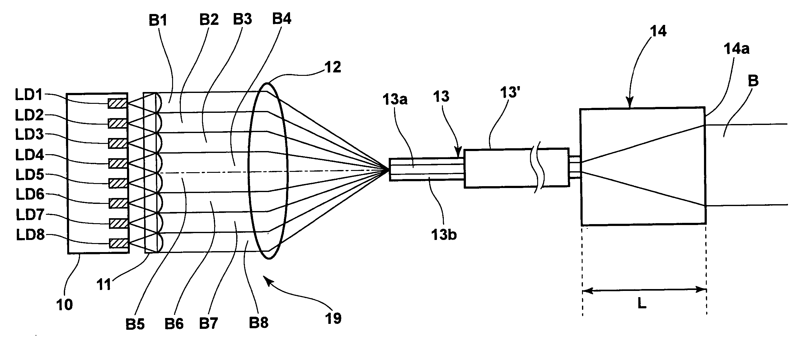
[0058] FIG. 1 is a diagram illustrating an outline of a laser apparatus according to the first embodiment of the present invention, and FIGS. 2 and 3 are schematic plan and side views of a module containing the laser apparatus of FIG. 1.

[0059] The laser apparatus of FIG. 1 is constituted by a heat block (heat-dissipation block) 10, GaN-based semiconductor laser chips LD1 through LD8, a collimator-lens array (microlens array) 11, a condensing lens 12, a multimode optical fiber 13, and a glass element 14.

[0060] The heat block 10 is made of copper or a copper alloy. The GaN-based semiconductor laser chips LD1 through LD8 are fixed on the heat block 10, and each of the GaN-based semiconductor laser chips LD1 through LD8 has a single cavity, and operates in a single transverse mode. The glass element 14 has a shape of a rectangular parallelopiped with a thickness L of about 2 mm, and is fixed to a light-emission end of the multimode optical fiber 13 by fusion.

[0061] Note that FIG. 1 show...

second embodiment

[0073] Next, the laser apparatus according to the second embodiment of the present invention will be explained below. The laser apparatus according to the second embodiment is different from the first embodiment in only the protection member which is arranged in a vicinity of a light-emission end face of a multimode optical fiber. Therefore, the explanations on the semiconductor laser elements, the optical condensing system, and the optical multiplex system are not repeated here unless necessary. FIG. 5 is a side view of the protection member in the laser apparatus according to the second embodiment.

[0074] As in the first embodiment, the multimode optical fiber is constituted by a core and a cladding surrounding the core, and the multimode optical fiber is covered with resin. In FIG. 5, the resin-covered multimode optical fiber is indicated by reference numeral 13'. In addition, as in the alternative construction of the first embodiment, the circumference of a portion 23 of the mult...

third embodiment

[0083] Next, the laser apparatus according to the third embodiment of the present invention will be explained below. The laser apparatus according to the third embodiment is different from the first embodiment in only the protection member which is arranged in a vicinity of a light-emission end of a multimode optical fiber. Therefore, the explanations on the semiconductor laser elements, the optical condensing system, and the optical multiplex system are not repeated here unless necessary. FIG. 6 is a plan view of the protection member in the laser apparatus according to the third embodiment of the present invention.

[0084] As illustrated in FIG. 6, a metalized portion 23 of the multimode optical fiber is fixed on a holder 34 in a package 30, which has a glass window 31 as a light-emission window. The package 30 has a gas inlet 32a and a gas outlet 32b. In addition, a gas circulation system comprising a filter 35, a pump 36, a valve 37, and a gas cylinder 38 is provided. The filter 3...


PUM


Abstract

In a laser apparatus, a plurality of semiconductor laser elements respectively emit laser beams; a multimode optical fiber has a light-entrance end and a light-emission end; an optical condensing system collects the laser beams emitted from the plurality of semiconductor laser elements, and couples the collected laser beams to the light-entrance end of the multimode optical fiber; and a protection member is arranged at the light-emission end of the multimode optical fiber, protects the light-emission end from the atmosphere, and has a light-emission window located at at least a predetermined distance from the light-emission end.

Description

[0001] 1. Field of the Invention[0002] The present invention relates to a laser apparatus in which laser beams emitted from a plurality of semiconductor laser elements are collected by an optical condensing system, and are optically multiplexed in an optical fiber.[0003] 2. Description of the Related Art[0004] The following documents (1) to (5) disclose information related to the present invention.[0005] (1) Japanese Unexamined Patent Publication No. 2002-202442 (corresponding to U.S. Patent Laid-Open No. 20020090172[0006] (2) Japanese Unexamined Patent Publication No. 11(1999)-54852[0007] (3) U.S. Pat. No. 5,392,305[0008] (4) Japanese Unexamined Patent Publication No. 11(1999)-167132 (corresponding to U.S. Pat. No. 6,404,786)[0009] (5) Japanese Unexamined Patent Publication No. 11 (1999)-87814[0010] Conventionally, in order to generate a laser beam having an ultraviolet wavelength, wavelength conversion lasers, excimer lasers, and Ar lasers are used. In the wavelength conversion la...

Claims


Application Information

Patent Timeline
IPC IPC(8): G02B6/42G02B27/00H01S5/022H01S5/323H01S5/40
CPCG02B6/4201G02B6/4249G02B6/4206G02B6/4273G02B6/424G02B6/4257G02B6/4254G02B27/00
Inventor NAGANO, KAZUHIKOOKAZAKI, YOJIKURAMACHI, TERUHIKOYAMANAKA, FUSAO
Owner FUJIFILM HLDG CORP
Why Eureka
Try Eureka