
Plasma generation and processing with multiple radiation sources

a radiation source and radiation source technology, applied in the direction of catalyst activation/preparation, energy-based chemical/physical/physicochemical processes, arc welding apparatus, etc., can solve the problems of multiple microwave energy sources being particularly susceptible to damage, single microwave energy sources can be damaged, and other problems, to achieve the effect of reducing the possibility of damag

Inactive Publication Date: 2004-01-01
BTU INTERNATIONAL
View PDF97 Cites 79 Cited by
  • Summary
  • Abstract
  • Description
  • Claims
  • Application Information

AI Technical Summary

Benefits of technology

"The present invention provides apparatus and methods for using multiple radiation sources, such as microwave radiation sources, to carry out high power plasma-assisted processes. The use of multiple radiation sources can reduce the possibility of damage to the plasma caused by its own radiation or from other sources. The invention also includes a plasma catalyst that can improve the environmental conditions required for igniting a plasma, and a method for forming a plasma using a dual-cavity system. The technical effects of the invention include improved plasma ignition, modulation, and sustainability, as well as improved plasma catalyst performance."

Problems solved by technology

A single microwave energy source can be damaged, however, when one source directs microwave energy into a plasma chamber that reflects the energy back toward the same source.
This can be especially problematic when there is no strong microwave absorber in the cavity, such as when a plasma is not yet formed.
Also, multiple microwave energy sources are particularly susceptible to damage when combined to ignite or sustain a plasma.
For example, a first source can be damaged when it directs microwave energy into a chamber because that energy could be directed into another simultaneously connected radiation source.
However, vacuum equipment, which is required to lower the gas pressure, can be expensive, as well as slow and energy-consuming.
Moreover, the use of such equipment can limit manufacturing flexibility.

Method used


Image

  • Plasma generation and processing with multiple radiation sources
  • Plasma generation and processing with multiple radiation sources
  • Plasma generation and processing with multiple radiation sources

Examples


Embodiment Construction

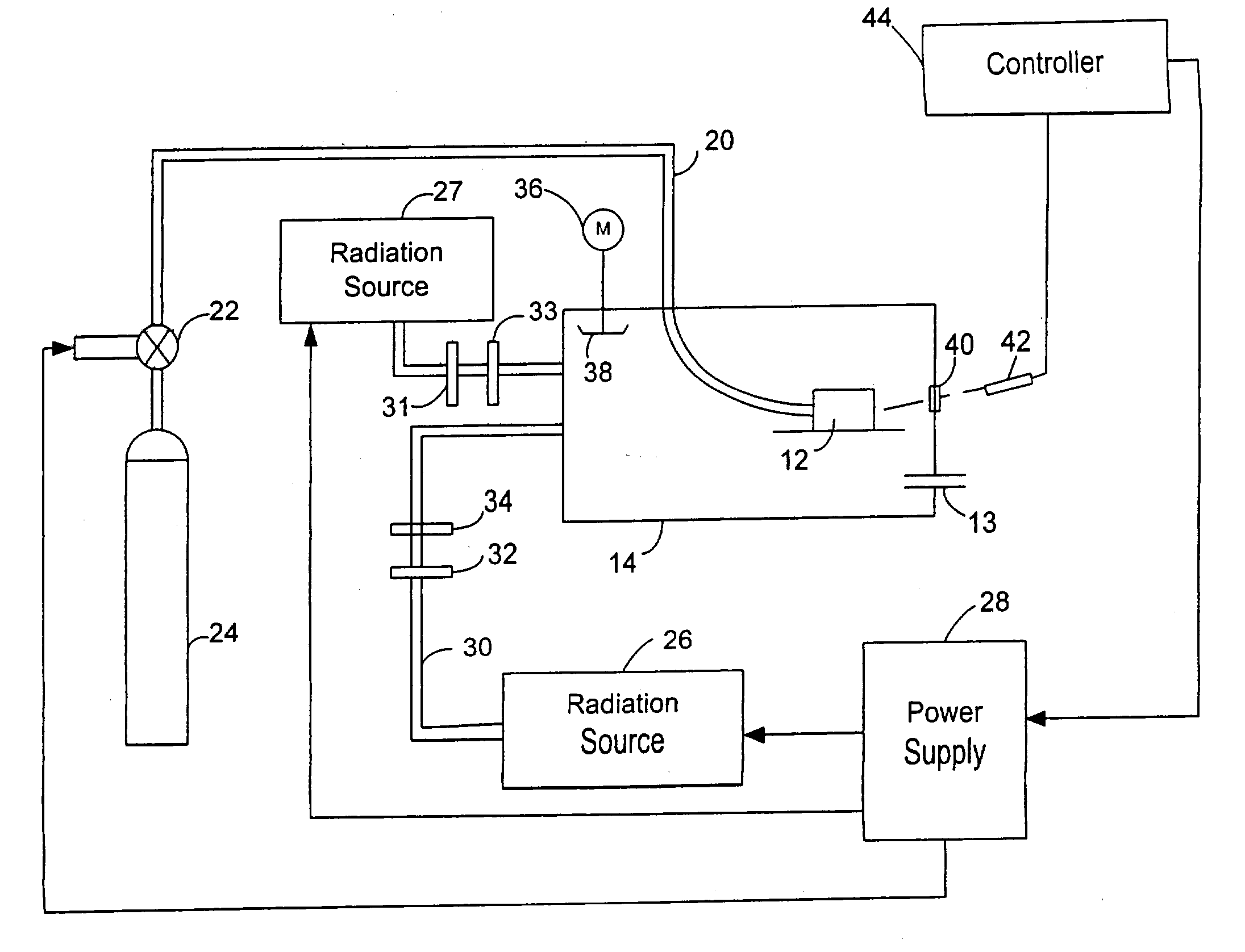
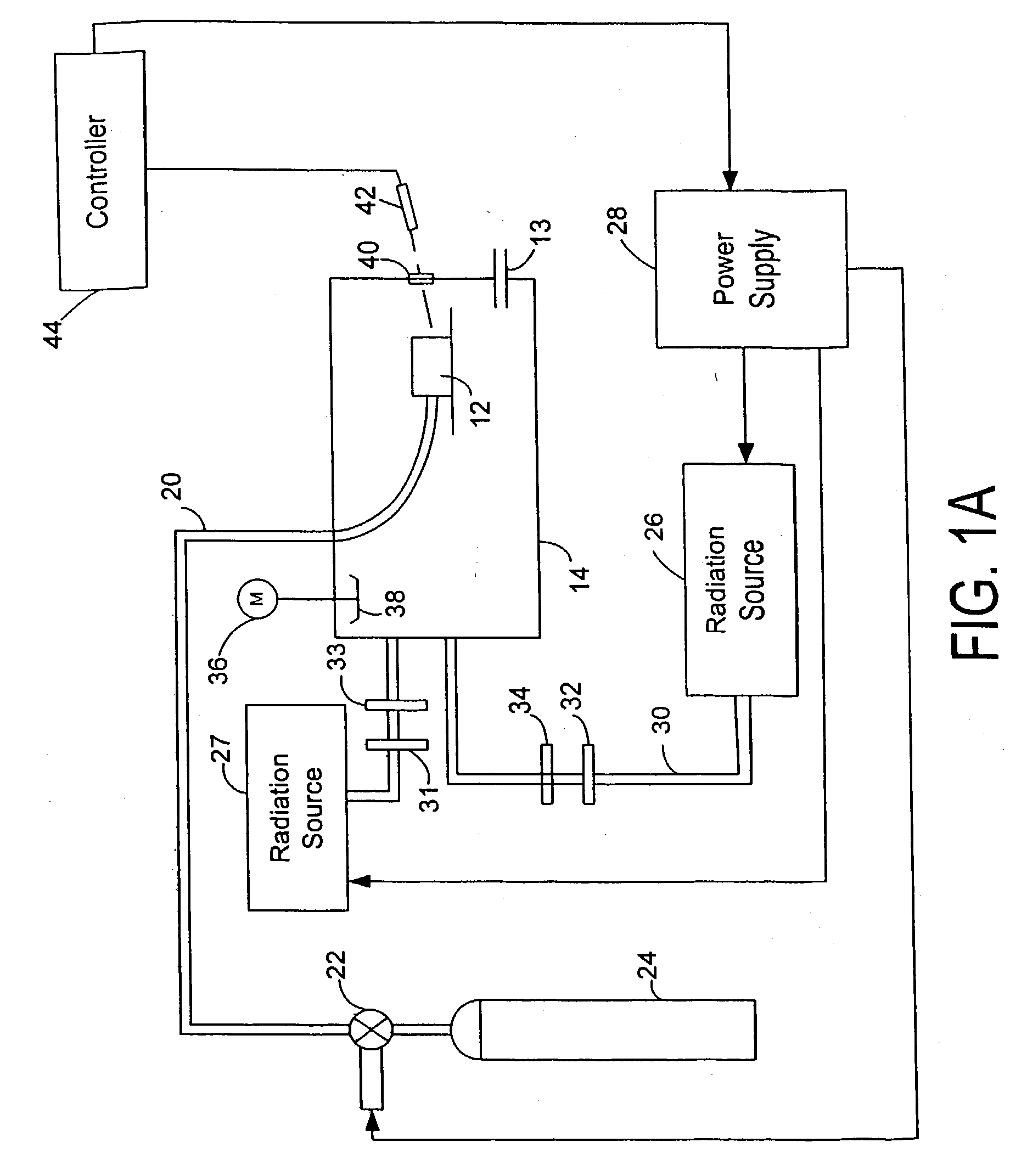
[0023] Consistent with the present invention, plasma apparatus and methods that use multiple radiation sources are provided. In one embodiment, as shown in FIG. 1A, a radiation apparatus may include cavity 12. Further, in one embodiment, the radiation apparatus may further include a plasma catalyst located proximate to the cavity, which may cooperate with the radiation to cause the gas to form a plasma.

[0024] This invention may further relate to methods and apparatus for initiating, modulating, and sustaining a plasma for a variety of applications, including heat-treating, synthesizing and depositing carbides, nitrides, borides, oxides, and other materials, doping, carburizing, nitriding, and carbonitriding, sintering, multi-part processing, joining, sintering, decrystallizing, making and operating furnaces, gas exhaust-treating, waste-treating, incinerating, scrubbing, ashing, growing carbon structures, generating hydrogen and other gases, forming electrodeless plasma jets, plasma ...


PUM

PropertyMeasurementUnit
frequencyaaaaaaaaaa
pressuresaaaaaaaaaa
temperaturesaaaaaaaaaa

Abstract

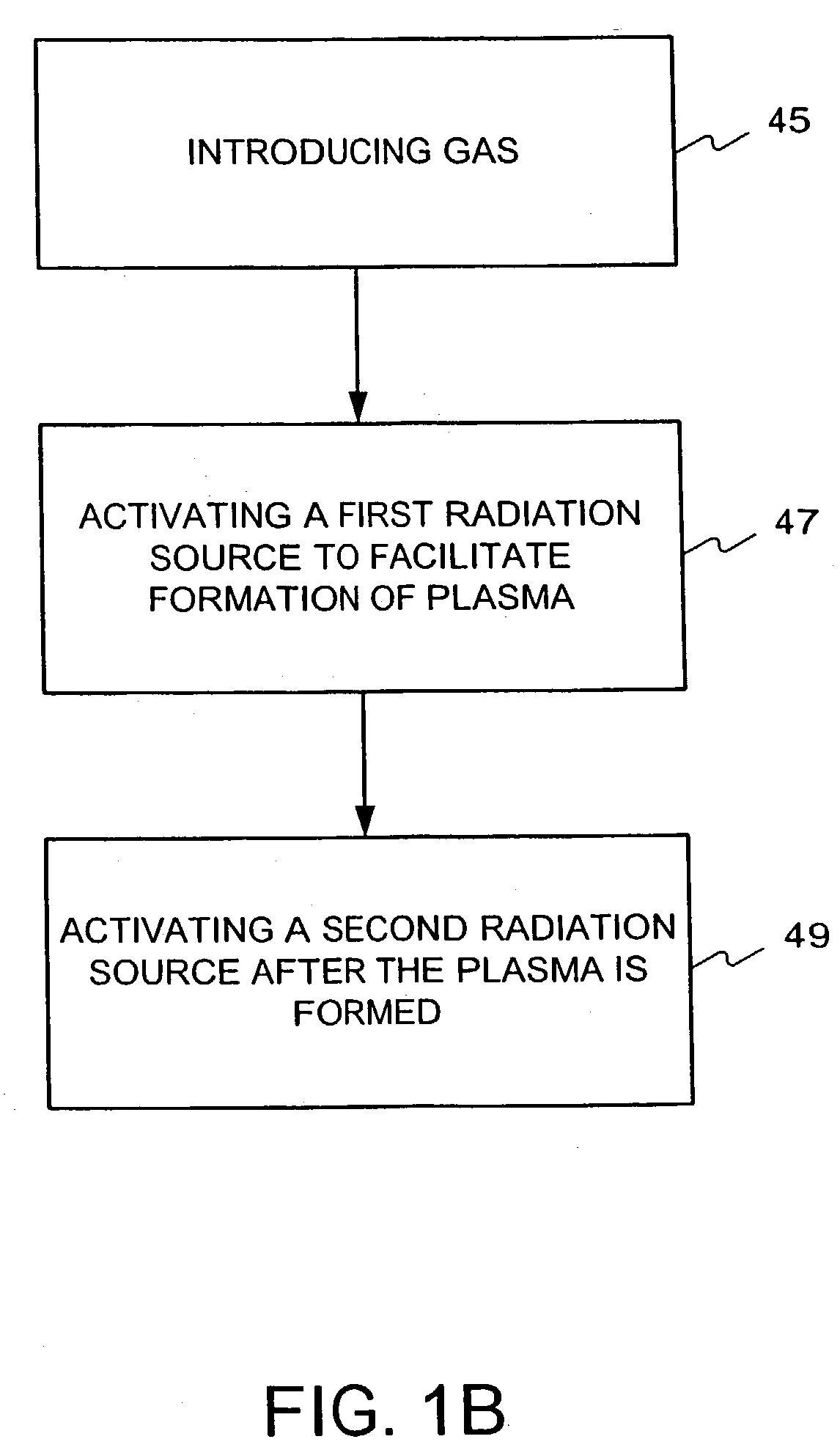
Plasma-assisted methods and apparatus that use multiple radiation sources are provided. In one embodiment, a plasma is ignited by subjecting a gas in a processing cavity to electromagnetic radiation having a frequency less than about 333 GHz in the presence of a plasma catalyst, which may be passive or active. A controller can be used to delay activation of one radiation source with respect to another.

Description

[0001] Priority is claimed to U.S. Provisional Patent Application No. 60 / 378,693, filed May 8, 2002, No. 60 / 430,677, filed Dec. 4, 2002, and No. 60 / 435,278, filed Dec. 23, 2002, all of which are fully incorporated herein reference.[0002] The invention relates to methods and apparatus for plasma-assisted processing, and in particular to using multiple electromagnetic radiation sources in combination.[0003] It is known that a single microwave radiation source can be used to generate a plasma by subjecting a gas to a sufficient amount of microwave radiation. A single microwave energy source can be damaged, however, when one source directs microwave energy into a plasma chamber that reflects the energy back toward the same source. This can be especially problematic when there is no strong microwave absorber in the cavity, such as when a plasma is not yet formed. Also, multiple microwave energy sources are particularly susceptible to damage when combined to ignite or sustain a plasma. Fo...

Claims


Application Information

Patent Timeline
Patent Type & Authority Applications(United States)
IPC IPC(8): A62D3/00B01J7/00B01D53/86B01D53/92B01J19/08B01J19/12B01J37/34B22F3/105C01B3/02C21D1/06C21D1/09C21D1/38C22B4/00F01N3/08F01N3/10F01N3/20F01N3/24F01N3/28F01N3/30F01N9/00F01N13/10F27B17/00F27D3/12F27D11/08F27D11/12G21K5/00H01J37/32H01M8/06H05B6/68H05B6/78H05B6/80H05H1/24H05H1/46
CPCB01D53/92Y02B40/143B01D2259/818B01J19/088B01J19/126B01J2219/00063B01J2219/00193B01J2219/002B01J2219/00213B01J2219/0024B01J2219/0892B01J2219/0894B01J2219/1269B82Y10/00B82Y30/00C22B4/005F01N3/202F01N3/206F01N13/10F01N2240/28F01N2610/08H01J37/32009H01J37/32192H01J37/32302H01J37/32366H01J2237/0206H01J2237/33H01J2237/336H01J2237/338H05B6/6402H05B6/68H05B6/806H05B2206/044H05H1/24H05H1/46Y02T10/26B01D2258/01Y02B40/00Y02T10/12H05H1/461H05H1/4652H01J37/32
Inventor KUMAR, SATYENDRAKUMAR, DEVENDRA
Owner BTU INTERNATIONAL
Learn More